


Chapter 4 121
Optimizing Performance
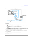
Using External Leveling
Configure the Signal Generator
1. Press
Preset.
2. Press
Frequency > 10 > GHz.
3. Press
Amplitude > 0 > dBm.
4. Press
RF On/Off.
5. Press
Leveling Mode > Ext Detector.
This deactivates the internal ALC detector and switches the ALC input path to the front panel
ALC INPUT connector. The EXT indicator is activated in the AMPLITUDE area of the display.
NOTE For signal generators with Option 1E1, notice that the ATTN HOLD (attenuator hold)
annunciator is displayed. During external leveling, the signal generator automatically
uncouples the attenuator from the ALC system for all external leveling points. While in
this mode, the RF output amplitude adjustment is limited to −20 to +25 dBm, the
adjustment range of the ALC circuitry. For more information, see “External Leveling with
Option 1E1 Signal Generators” on page 122.
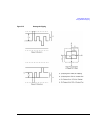
6. Observe the coupling factor printed on the directional coupler at the detector port. Typically, this
value is −10 to −20 dB.
Enter the positive dB value of this coupling factor into the signal generator.
7. Press
More (1 of 2) > Ext Detector Coupling Factor > 16 (or the positive representation of the value listed at
the detector port of the directional coupler) >
dB.
Leveled output power is now available at the output of the directional coupler.
NOTE While operating in external leveling mode, the signal generator’s displayed RF output
amplitude is affected by the coupling factor value, resulting in a calculated approximation of
the actual RF output amplitude. To determine the actual RF output amplitude at the point of
detection, measure the voltage at the external detector output and refer to Figure 4-3 or
measure the power directly with a power meter.
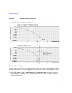
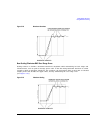
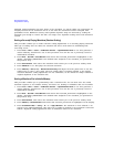
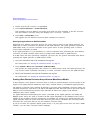
Determining the Leveled Output Power
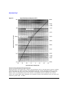
Figure 4-3 shows the input power versus output voltage characteristics for typical Agilent
Technologies diode detectors. Using this chart, you can determine the leveled power at the diode
detector input by measuring the external detector output voltage. You must then add the coupling
factor to determine the leveled output power. The range of power adjustment is approximately -20 to
+25 dBm.