


232 Chapter 11
Peripheral Devices
N5102A Digital Signal Interface Module
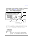
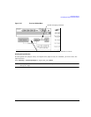
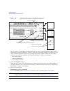
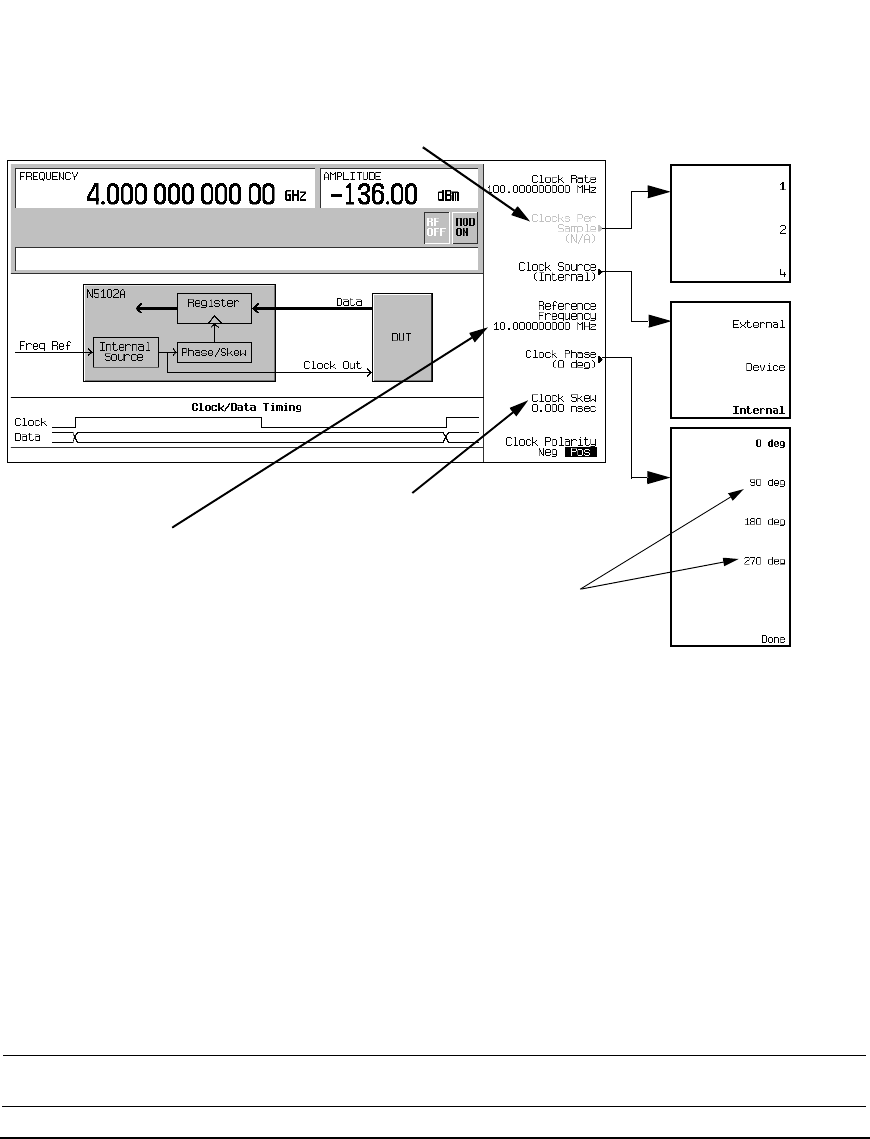
Figure 11-18 Clock Setup Softkey Menu for a Parallel Port Configuration
The top graphic on the display shows the current clock source that provides the output clock
signal at the Clock Out and Device Interface connectors. The graphic changes to reflect the clock
source selection discussed later in this procedure. The bottom graphic shows the clock edges
relative to the data. The displayed clock signal will change to reflect the following:
• clock phase choice
•clock skew adjustment
• clock polarity selection
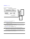
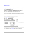
2. Press the
Clock Source softkey.
From this menu, select the clock signal source. With each selection, the clock routing display in
the signal generator clock setup menu will change to reflect the current clock source. This will be
indicated by a change in the graphic.
3. Select the clock source.
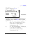
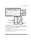
If External or Device is Selected
Press the
Clock Rate softkey and enter the clock rate of the externally applied clock signal.
NOTE The clock phase and clock skew may need to be adjusted any time the clock rate setting is
changed. Refer to “Clock Timing for Phase and Skew Adjustments” on page 215.
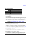
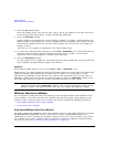
Inactive for Input mode
Active for only the Internal clock source selection
Inactive for clock rates below 25 MHz
Inactive for clock rates below
10 MHz and above 200 MHz