


Chapter 11 233
Peripheral Devices
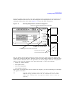
N5102A Digital Signal Interface Module
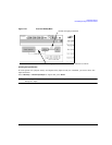
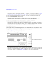
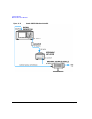
For the External selection, the signal is supplied by an external clock source and applied to the Ext
Clock In connector. For the
Device selection, the clock signal is supplied through the Device
Interface connector, generally by the device being tested.
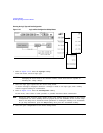
If Internal is Selected
Using an external frequency reference, the N5102A module generates its own internal clock signal.
The reference frequency signal must be applied to the Freq Ref connector on the digital module.
a. Press the
Reference Frequency softkey and enter the frequency of the externally applied frequency
reference.
b. Press the
Clock Rate softkey and enter the appropriate clock rate.
Table 11-9 provides a quick view of the settings and connections associated with each clock
source selection.
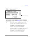
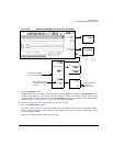
4. Press the
Clock Phase softkey.
From the menu that appears, the phase of the clock relative to the data can be changed in
90 degree increments. The selections provide a coarse adjustment for positioning the clock on the
valid portion of the data. Selecting 180 degrees is the same as selecting a negative clock polarity.
The 90 degree and 270 degree selections are not available when the clock rate is set below
10 MHz or above 200 MHz. If 90 degrees or 270 degrees is selected when the clock rate is set
below 10 MHz or above 200 MHz, the phase will change to 0 degrees or 180 degrees, respectively.
NOTE The clock phase and clock skew may need to be adjusted any time the clock rate setting is
changed. Refer to “Clock Timing for Phase and Skew Adjustments” on page 215.
5. Enter the required phase adjustment.
6. Press the
Return softkey to return to the clock setup menu.
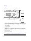
7. Press the
Clock Skew softkey.
This provides a fine adjustment for the clock relative to its current phase position. The skew is a
phase adjustment using increments of time. This enables greater skew adjustment capability at
higher clock rates. For clock rates below 25 MHz, this softkey is inactive.
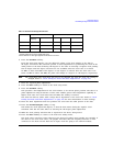
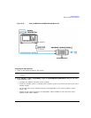
Table 11-9 Clock Source Settings and Connectors
Clock Source Softkeys N5102A Module Connection
Reference
Frequency
Clock Rate
a
a.For the Internal selection, this sets the internal clock rate. For the External and Device selections, this tells the
interface module the rate of the applied clock signal.
Freq Ref Ext Clock In Device Interface
External • •
Device • •
Internal
b
b.There should be no clock signal applied to the Ext Clock In connector when Internal is being used.
•• •