


22 Chapter 1
Signal Generator Overview
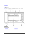
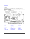
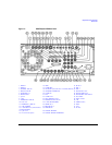
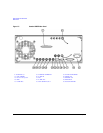
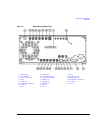
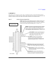
Rear Panel
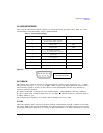
1. EVENT 1
This female BNC connector is used with an internal baseband generator (Option 601/602). On signal
generators without Option 601/602, this female BNC connector is non-functional.
In real-time mode, the EVENT 1 connector outputs a pattern or frame synchronization pulse for
triggering or gating external equipment. It may be set to start at the beginning of a pattern, frame, or
timeslot and is adjustable to within ± one timeslot with one bit resolution.
In arbitrary waveform mode, the EVENT 1 connector outputs a timing signal generated by Marker 1.
A marker (3.3 V CMOS high for both positive and negative polarity) is output on the EVENT 1
connector whenever a Marker 1 is turned on in the waveform.
The reverse damage levels for this connector are > +8 V and < −4 V. The nominal output impedance
is not defined.
2. EVENT 2
This female BNC connector is used with an internal baseband generator (Option 601/602). On signal
generators without Option 601/602, this female BNC connector is non-functional.
In real-time mode, the EVENT 2 connector outputs a data enable signal for gating external
equipment. This is applicable when external data is clocked into internally generated timeslots. Data
is enabled when the signal is low.
In arbitrary waveform mode, the EVENT 2 connector outputs a timing signal generated by Marker 2.
A marker (3.3 V CMOS high for both positive and negative polarity) is output on the EVENT 2
connector whenever a Marker 2 is turned on in the waveform.
The reverse damage levels for this connector are > +8 V and < −4 V. The nominal output impedance
is not defined.
3. PATTERN TRIG IN
This female BNC connector is used with an internal baseband generator (Option 601/602). On signal
generators without Option 601/602, this female BNC connector is non-functional. This connector
accepts a signal that triggers an internal pattern or frame generator to start a single-pattern output.
Minimum pulse width is 100 ns. Damage levels are > +5.5 V and < −0.5 V. The nominal input
impedance is not defined.
4. BURST GATE IN
This female BNC connector is used with an internal baseband generator (Option 601/602). On signal
generators without Option 601/602, this connector is non-functional. This connector accepts a 3-volt
CMOS input signal for gating burst power. Burst gating is used when you are externally supplying
data and clock information.
The input signal must be synchronized with the external data input that will be output during the
burst. The burst power envelope and modulated data are internally delayed and re-synchronized. The
input signal must be CMOS high for normal burst RF power or CW RF output power and CMOS low
for RF off. Damage levels are > +5.5 V and < −0.5 V. The nominal input impedance is not defined.