


90 Chapter 3
Basic Digital Operation
Using Waveform Markers
Saving Marker Polarity and Routing Settings
Marker polarity and routing settings remain until you reconfigure them, preset the signal generator,
or cycle the PSG power. To ensure that a waveform uses the correct settings when it is played, set
the marker polarities or routing (RF Blanking and ALC Hold), and save the information to the file
header (page 72). This is especially important when the segment plays as part of a sequence because
the previously played segment could have different marker and routing settings.
ALC Hold Marker Function (For Instruments with serial prefixes >=US4722/MY4722)
While you can set a marker function (described as
Marker Routing on the softkey label) either before or
after you set marker points (page 95), setting a marker function before setting marker points may
cause power spikes or loss of power at the RF output.
Use the ALC hold function by itself when you have a waveform signal that incorporates idle periods,
or when the increased dynamic range encountered with RF blanking (page 100) is not desired.
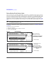
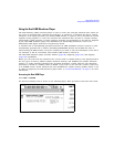
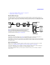
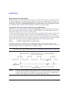
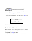
The ALC hold marker function holds the ALC circuitry at the average (RMS) value of the sampled
points set by the marker(s). For both positive and negative marker polarity, the ALC samples the RF
output signal (the carrier plus any modulating signal) when the marker signal goes high:
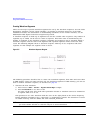
The marker signal has a minimum of a two sample point delay in its response relative to the
waveform signal response. To compensate for the marker signal delay, offset marker points from the
waveform sample at which you want the ALC sampling to begin.
NOTE Because it can affect the waveform’s output amplitude, do not use the ALC hold for longer
than 100 ms. For longer time intervals, refer to “Setting Power Search Mode” on page 247.
CAUTION Incorrect ALC sampling can create a sudden unleveled condition that may create a spike
in the RF output, potentially damaging a DUT or connected instrument. To prevent this
condition, ensure that you set markers to let the ALC sample over an amplitude that
accounts for the higher power levels encountered within the signal.
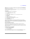
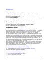
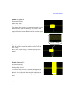
Positive: The signal is sampled during the on marker points.
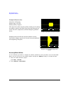
Negative The signal is sampled during the off marker points.
Positive Polarity