


Chapter 1 27
Signal Generator Overview
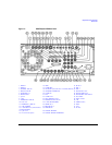
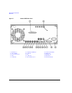
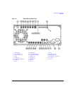
Rear Panel
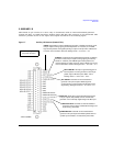
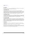
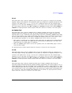
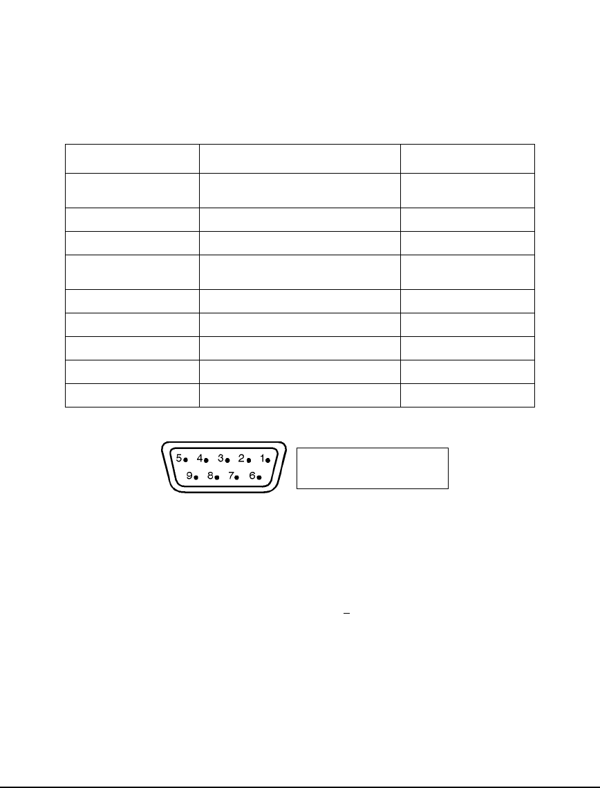
19. AUXILIARY INTERFACE
This 9-pin D-subminiature female connector is an RS-232 serial port that can be used for serial
communication and Master/Slave source synchronization.
Figure 1-8
20. 10 MHz IN
This female BNC connector accepts an external timebase reference input signal level of > −3dBm.
The reference must be 1, 2, 2.5, 5, or 10 MHz, within ±1 ppm. The signal generator detects when a
valid reference signal is present at this connector and automatically switches from internal to
external reference operation.
For Option UNR/UNX or instruments with serial prefixes >
US4805/MY4805, this BNC connector
accepts a signal with a nominal input level of 5 ±5 dBm. The external frequency reference must be
10 MHz, within ±1 ppm.
The nominal input impedance is 50 ohms with a damage level of ≥ 10 dBm.
21. LAN
This LAN interface allows ethernet local area network communication through a 10Base-T LAN cable.
The yellow LED on the interface illuminates when data transmission (transfer/receive) is present. The
green LED illuminates when there is a delay in data transmission or no data transmission is present.
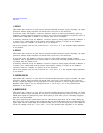
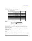
Table 1-3 Auxiliary Interface Connector
Pin Number Signal Description Signal Name
1 No Connection (default operation)/
Retrace (Master/Slave operation)
2 Receive Data RECV
3 Transmit Data XMIT
4 +5V (Default operation)/
Sweep Stop (Master/Slave operation)
5Ground, 0V
6No Connection
7Request to SendRTS
8Clear to SendCTS
9No Connection
View looking into
rear panel connector