


24 Chapter 1
Signal Generator Overview
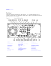
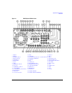
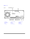
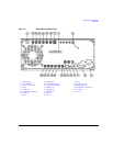
Rear Panel
6. DIGITAL BUS
This is a proprietary bus used for Agilent Baseband Studio products, which require an E8267D with
Options 003/004 and 601/602. This connector is not operational for general-purpose customer use.
Signals are present only when a Baseband Studio option is installed (for details, refer to
http://www.agilent.com/find/basebandstudio). The DIG BUS annunciator appears on the display when
the Digital Bus is active (and the internal oven reference oscillator is not cold—OVEN COLD appears in
this same location).
7. Q OUT
This female BNC connector (E8267D only) is used with an internal baseband generator
(Option 601/602) to output the analog, quadrature-phase component of I/Q modulation. On signal
generators without Option 601/602, this female BNC connector is used to output the
quadrature-phase component of an external I/Q modulation that has been fed into the Q input
connector. The nominal output impedance of the Q OUT connector is 50 ohms, dc-coupled.
8. I OUT
This female BNC connector (E8267D only) is used with an internal baseband generator
(Option 601/602) to output the analog, in-phase component of I/Q modulation. On signal generators
without Option 601/602, this female BNC connector is used to output the in-phase component of an
external I/Q modulation that has been fed into the I input connector. The nominal output impedance
of the I OUT connector is 50 ohms, dc-coupled.
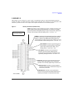
9. WIDEBAND I INPUTS
These female SMA connectors: I IN (+) and I-bar IN (−) (Option 016 only) are used with differential
wideband external I/Q inputs. They accept wideband AM and allow direct high–bandwidth analog
inputs to the I/Q modulator in the 3.2−44 GHz range (frequency limit is dependant on the option).
This input is not calibrated. The recommended input power level is −1 dBm with a +/− 1 VDC input
voltage. The nominal impedance for this connector is 50 ohms.
The signal generator uses lowside mixing in the 20–28.5 GHz frequency range (Options 532 and 544),
which reverses the phase relationship for I and Q signals. For internally generated I/Q signals the
signal generator’s firmware compensates for this. However, for wideband external I/Q inputs
(Option 016) there is no compensation and the I and Q inputs at the rear panel must be reversed to
maintain the correct phase relationships in this frequency band. Refer to the Data Sheet and to the
A37 Upconverter description in the Service Guide for more information.
For instruments with Option 015 (discontinued), single-ended wideband I/Q, there is a single BNC I
input. The recommended power level at this input connector is 0 dBM.