


Chapter 11 217
Peripheral Devices
N5102A Digital Signal Interface Module
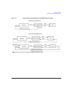
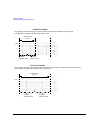
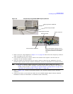
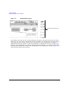
Figure 11-8 Example Setup using the PSG 10 MHz Frequency Reference
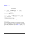
1. Refer to the five setup diagrams in Figure 11-3 on page 209 and connect the frequency reference
cable according to the clock source.
2. If an external clock source is used, connect the external clock signal to the Ext Clock In
connector on the interface module.
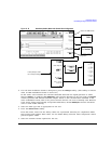
3. Select the break-out board that has the output connector suited for the application. See the
N5102A Digital Signal Interface Module Installation Guide for information on breakout boards.
NOTE If the Device Interface mating connector is used with the device under test, refer to
Figure 11-8 for the device interface connection and connect the device to the N5102A
module. Then proceed to “Operating the N5102A Module in Output Mode” on page 219 or
“Operating the N5102A Module in Input Mode” on page 228.
4. Refer to Figure 11-8. Connect the breakout board to the N5102A module’s Device Interface
connector.
5. Connect the device to the break-out board. See the N5102A Digital Signal Interface Module
Installation Guide for information on breakout board connectivity.
Signal generator 10 MHz Out
Freq Ref connector
Device interface connection
Device under test
Break-out board
User furnished ribbon cable(s) connect
between the device and break-out board.
Common Freq Ref cable
The clock to the device is in the ribbon
cable.