


216 Chapter 11
Peripheral Devices
N5102A Digital Signal Interface Module
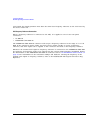
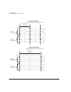
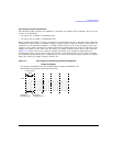
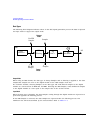
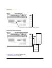
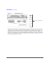
Figure 11-7 Clock Phase and Skew Adjustments
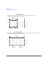
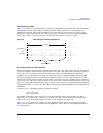
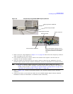
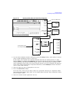
Connecting the Clock Source and the Device Under Test
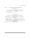
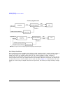
As shown in Figure 11-3 on page 209, there are numerous ways to provide a common frequency
reference to the system components (PSG, N5102A module, and the device under test). Figure 11-8
shows an example setup where the signal generator supplies the common frequency reference and the
N5102A module provides the clock to the device.
See the N5102A Digital Signal Interface Module Installation Guide for detailed information on
device interface connections.
CAUTION The Device Interface connector on the interface module communicates using high speed
digital data. Use ESD precautions to eliminate potential damage when making
connections.
NOTE You must disconnect the digital bus cable and the digital module while downloading
firmware to the PSG.
Clock skew adjustment
90 degree phase adjustment
Clock
Phase adjusted
skew adjusted
clock
clock
Data
Phase and