


Chapter 11 203
11 Peripheral Devices
This chapter provides information on peripheral devices used with PSG signal generators. The
N5102A Baseband Studio digital signal interface module and extended frequency source module
operation and features are described in the following sections:
N5102A Digital Signal Interface Module
• “Clock Timing” on page 203
• “Connecting the Clock Source and the Device Under Test” on page 216
• “Data Types” on page 218
• “Operating the N5102A Module in Output Mode” on page 219
• “Operating the N5102A Module in Input Mode” on page 228
Millimeter-Wave Source Modules
• “Using Agilent Millimeter-Wave Source Modules” on page 236
• “Using Other Source Modules” on page 240
N5102A Digital Signal Interface Module
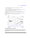
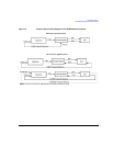
Clock Timing
This section describes how clocking for the digital data is provided. Clock timing information and
diagrams are supplied for the different port configurations (serial, parallel, or parallel interleaved
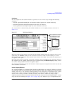
data transmission) and phase and skew settings. All settings for the interface module are available on
the signal generator user interface (UI).
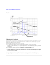
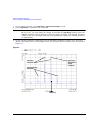
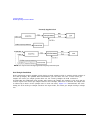
Clock and Sample Rates
A sample is a group of bits where the size of the sample is set using the
Word Size softkey. The clock is
the signal that tells when the bits of a sample are valid (in a non-transition state). The clock and
sample rates are displayed in the first-level and data setup softkey menus. The clock rate and sample
rate are usually the same. They will differ when serial mode is selected, or when there are multiple
clocks per sample.