Serial Port Pin 9 73
E-EQ-VX5RG-G-ARC VX5 Reference Guide
Serial Port Pin 9
Pin 9 of the serial ports may be configured to provide RI or +5V using DIP switches accessible by
removing the access cover:
• Pin 9 must be set to +5V if an external serial scanner is to be attached. This is the
default setting for COM1 and provides 400mA maximum.
• Pin 9 must be set to RI if a serial printer or PC cable is to be used with the port. This
is the default setting for COM2.
Note: COM2 is labeled either “COM2” or “COM2/3”.
Equipment Needed: Phillips No. 1 screwdriver, a Torque wrench capable of measuring to 9±1
inch pounds (1.016 ±.11 N/m).
Note: Torquing tool is not supplied by LXE.
1. Turn the VX5 off and remove the power supply before opening the access cover located
on the top of the VX5.
2. Loosen the three (3) Phillips screws securing the access cover so the cover can be
removed. The screws are a captive part of the cover and cannot be removed.
3. Remove the access cover. The cover is tethered to the VX5 to prevent loss.
COM1COM2
SCANNER
SERIAL
USB
IDE DRIVE
CARD BUS A
CARD BUS B
PCMCIA/CF ATA
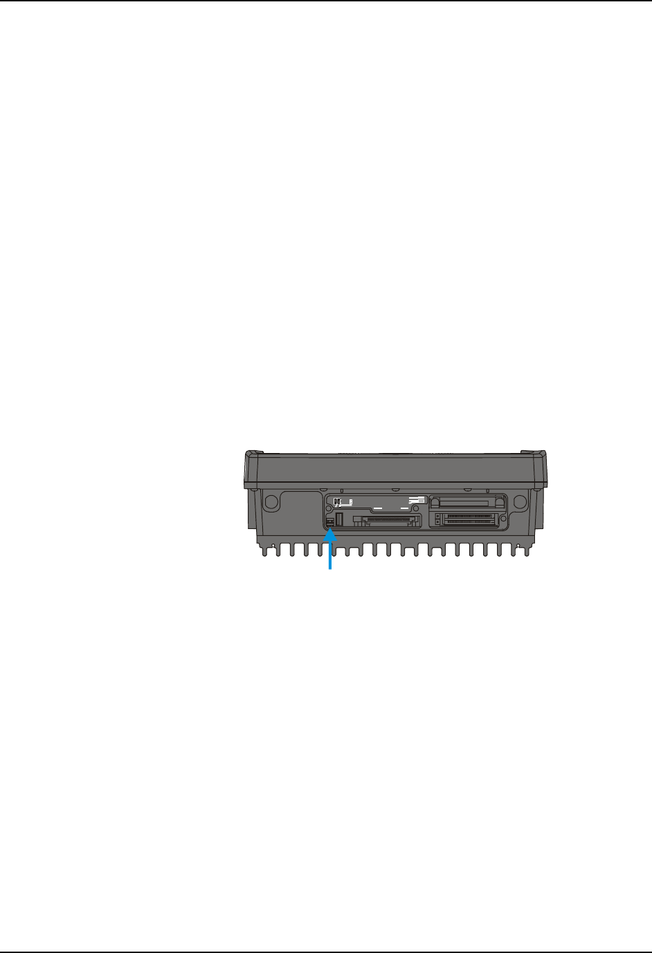
Figure 3-1 DIP Switch Location
Note: The tethered access panel cover is not shown in the illustration above.
4. Refer to the legend above the DIP switches. There are two DIP switches, one for
COM1 and one for COM2. When a DIP switch is in the Up position, the COM port pin
9 is configured for a scanner (+5V). When a DIP switch is in the Down position, the
COM port pin 9 is configured for RI.
5. After setting the DIP switches to the desired position, reattach the access cover screws
using a torque wrench capable of measuring 9±1 inch pounds (1.016±.11 N/m). The
three screws must be fastened to 9 inch pounds each. The screws require a Phillips size
1 driver head.
