


Groundsmaster 4000--D/4010--D Hydraulic SystemPage 4 -- 51
Procedurefor Rear Traction CircuitRelief Valve (R
V)
Pressure
Test
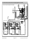
NOTE: Adjustable relief valve (RV) in the rear traction
control manifold reduces rear axle motor pressure
created in down hill, dynamic braking conditions to pre-
vent rear wheel lock up.
CAUTION
Prevent personal injury and/or damage to equip-
ment. Read all WARNINGS, CAUTIONS and Pre-
cautions for Hydraulic Testing at the beginning
of this section.
1. Park machine on a level surface with the cutting
decks lowered and off. Make sure hydraulic oil is at nor-
mal operating temperature, engine isoff and theparking
brake is applied.
NOTE: This test uses the same pressure gauge posi-
tion asusedto measure reversetraction circuitreducing
valve (PR) pressure.
NOTE: The #6 zero leak plug on the inside of rear trac-
tion m a nifold is a zero leak plug that has a tapered seal-
ing surface on the plug head. Lightly rap the plug head
using a punch and hammer before using an allen
wrench to remove the plug: the impact will allow plug re-
moval with less chance of damage to the socket head of
the plug.
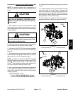
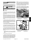
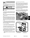
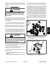
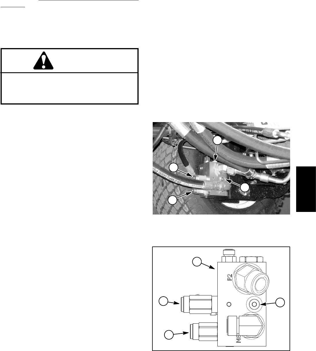
2. Locate rear traction manifold t hat is attached to the
front frame next to the left side front wheel (Fig. 34). Re-
move #6 zero leak plug on inside of rear traction mani-
fold and install diagnostic fitting (Toro part number
59--7410) into manifold port.
3. Connecta1000 PSI(70 bar)pressure gaugewithhy-
draulic hose attached to installed diagnostic fitting.
4. Start engine and increase engine speed to high idle
speed. Make sure that HI /LOW switch is in the LOW
(mow) position and release the parking brake.
5. OperatethemachineinLOWspeed(mow)withthe
cutting decks lowered. Drivedownaslopeinaforward
direction, decrease pressure on the traction pedal and
monitor the pressure gauge. Pressure should increase
until the rear traction circuit relief valve lifts.
GAUGE READING TO BE approximately 650 PSI
(45 bar) when the rear traction relief valve (RV)
opens.
6. Stop engine and record test results.
NOTE: If the rear traction circuit reducing valve (PR)
pressure is excessive, operation of the rear traction re-
lief valve (RV) may be affected. Before adjusting rear
traction relief valve (RV), make sure that pressure redu-
cing valve (PR) pressure is correct.
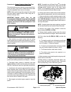
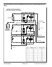
7. The rear traction circuitrelief valve (RV)is located on
the rear side of the rear traction manifold (Figs. 34 and
35). If test pressure is incorrect, adjust relief valve (RV)
(see Adjust Control Manifold Relief Valves in the Adjust-
ments section of this chapter).
8. When testing is completed, disconnect pressure
gauge from the installed diagnostic fitting. Remove
diagnostic fitting from manifold and install removed plug
into manifold. Torque plug to 25 ft--lb (34 N--m).
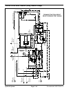
1. Rear traction manifold
2. #6 z ero leak plug
3. Relief(RV)valve
4. Reducing (PR) valve
Figure 34
2
1
3
4
1. Rear traction manifold
2. #6 z ero leak plug
3. Relief(RV)valve
4. Reducing (PR) valve
Figure 35
1
2
3
4
Hydraulic
System