


Groundsmaster 4000--D/4010--DPage 5 -- 30Electrical System
Component Testing
For accurate resistance and/or continuity checks, elec-
trically disconnect the component being tested from the
circuit (e.g. unplug the ignition switch connector before
checking continuit y on the switch).
NOTE: For engine component testing information, see
the Yanmar Workshop Manual and Yanmar
Troubleshooting Manual.
CAUTION
When testing electrical components f or continu-
ity with a multimeter (ohms setting), make sure
that power to the circuit has been disconnected.
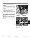
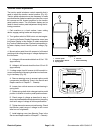
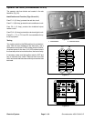
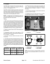
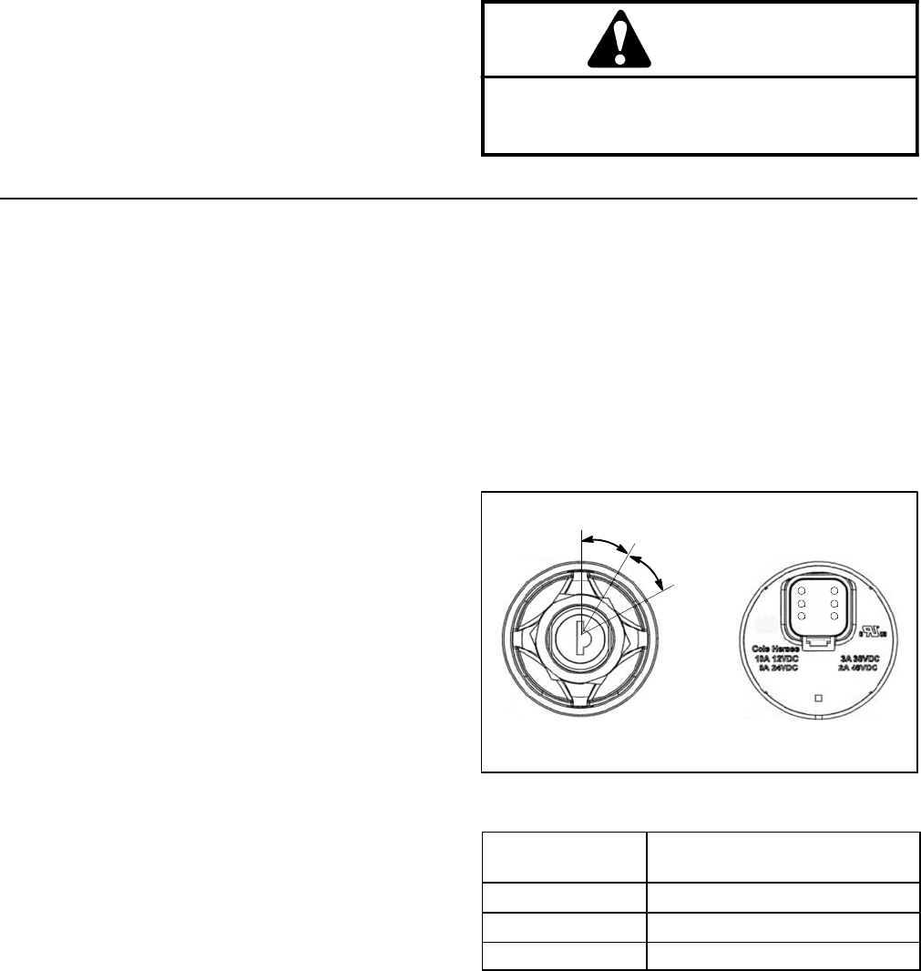
Ignition Switch
The ignition (key) switch is located on the control panel
and has three (3) positions: STOP, RUN and START
(Fig. 26). The To ro Electronic Controller (TEC) monitors
the operation of the ignition switch.
Testing
1. Park machine on a level surface, lower cutting
decks, engage parking brake and stop engine. Remove
key from ignition switch.
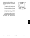
2. Before disconnecting the ignition switch for testing,
the switch and its circuit wiring should be tested as a
TEC electrical input using the InfoCenter Display (see
InfoCenter Display in this chapter). If input testing veri-
fies that the ignition switch and circuit wiring are func-
tioning correctly, no further ignition switch testing is
necessary. If, however, input testing determines that the
ignition switch and circuit wiring are not functioning cor-
rectly, proceed with the following ignition switch testing
procedure.
3. Remove controlarm coversto gain accessto ignition
switch (see Control Arm in the Service and Repairs sec-
tion of Chapter 7 -- Chassis).
4. Make sure ignition switch is in the OFF position. Dis-
connect wire harness connector from ignition switch.
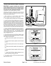
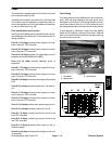
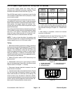
5. Theignitionswitchterminals are identified in Figure
26 and the circuitry of the switch is shown in the chart in
Figure 27. With the use of a multimeter (ohms setting),
the switch functions can be tested to determine whether
continuity exists between the various terminals for each
switch position. Verify continuity between switch termi-
nals.
6. Replace ignition switch if testing determines that it is
faulty.
7. If the ignition switchtests correctly anda circuit prob-
lem still exists, check wire harness(see Electrical Sche-
matics and Wire Harness Drawings in Chapter 10 --
Foldout Drawings).
8. After testing is complete, connect machine wire har-
ness connector to ignition switch. Secure control arm
covers to machine with removed fasteners (see Control
Arm in the Service and Repairs section of Chapter 7 --
Chassis).
Figure 26
REAR VIEW
FRONT VIEW
START
STOP
RUN
3
2
4
5
6
1
SWITCH
POSITION
CIRCUITS
STOP 1+6
RUN 1+3+4+5+6
START 1+2+4+5+6
Figure 27
NOTE: Ignition switch terminals 1 and 6 are connected
internally.Terminals4 and5 arealso connectedinternal-
ly. These terminals should have continuity regardless of
switch position.