


Groundsmaster 4000--D/4010--DPage 5 -- 48Electrical System
Relays with Five (5) Terminals
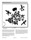
Your Groundsmaster uses a number of electrical relays
that have five (5) terminals. A tag near the wire harness
relay connector can be used to identify each relay.
The air conditioning relayis usedto controlthe aircondi-
tioning electrical power circuit on the Groundsmaster
4010--D. When energized by the air conditioning switch,
the relay provides current for the air conditioning com-
ponents.
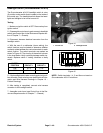
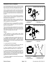
The main relay is used on models 30603 and 30605 to
provide current for several engine components when
energized by the engine ECU.
The rack actuator relay is used on models 30603 and
30605 to provide current for the engine rack actuator
when energized by the engine ECU.
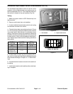
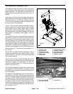
The EGR relay is u sed on models 30607 and 3 0609 to
provide current to the engine EGR valve when ener-
gized by the engine ECU.
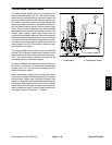
The air conditioning relay is attached to thecab headlin-
er above the switch panel. The main, rack actuator and
EGR relays are attached to the controller mount on the
right side of the engine (Fig. 59 or 60).
Testing
1. Park machine on a level surface, lower cutting
decks, stop engine, engage parking brake and remove
key from the ignition switch.
2. To make sure that machine operation does not occur
unexpectedly, disconnect negative (--) cable from bat-
tery and then disconnect positive (+) cable from battery
(see Battery Service in the Service and Repairs section
of this chapter).
3. Locate relay that is to be tested.
4. Disconnect wire harness connector from relay. Re-
move relay from mounting bracket for testing.
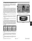
5. Using a multimeter, verify that coil resistance be-
tween terminals 85 and 86 is from 71 to 88 ohms.
6. Connect multimeter(ohms setting)leads torelay ter-
minals 30 and 87. Ground terminal 86 and apply +12
VDC to terminal 85. The relay should make and break
continuity between terminals 30 and 87 as +12 VDC is
applied and removed from terminal 85.
7. Disconnect voltage from terminal 85 and multimeter
lead from terminal 87.
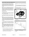
1. Controller mount
2. Engine ECU
3. Main relay
4. Rack actuator relay
Figure 59
MODELS 30603 AND 30605
1
3
2
4
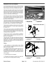
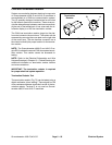
1. Controller mount
2. Engine ECU
3. EGR relay
Figure 60
MODELS 30607 AND 30609
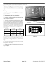
2
3
1
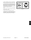
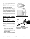
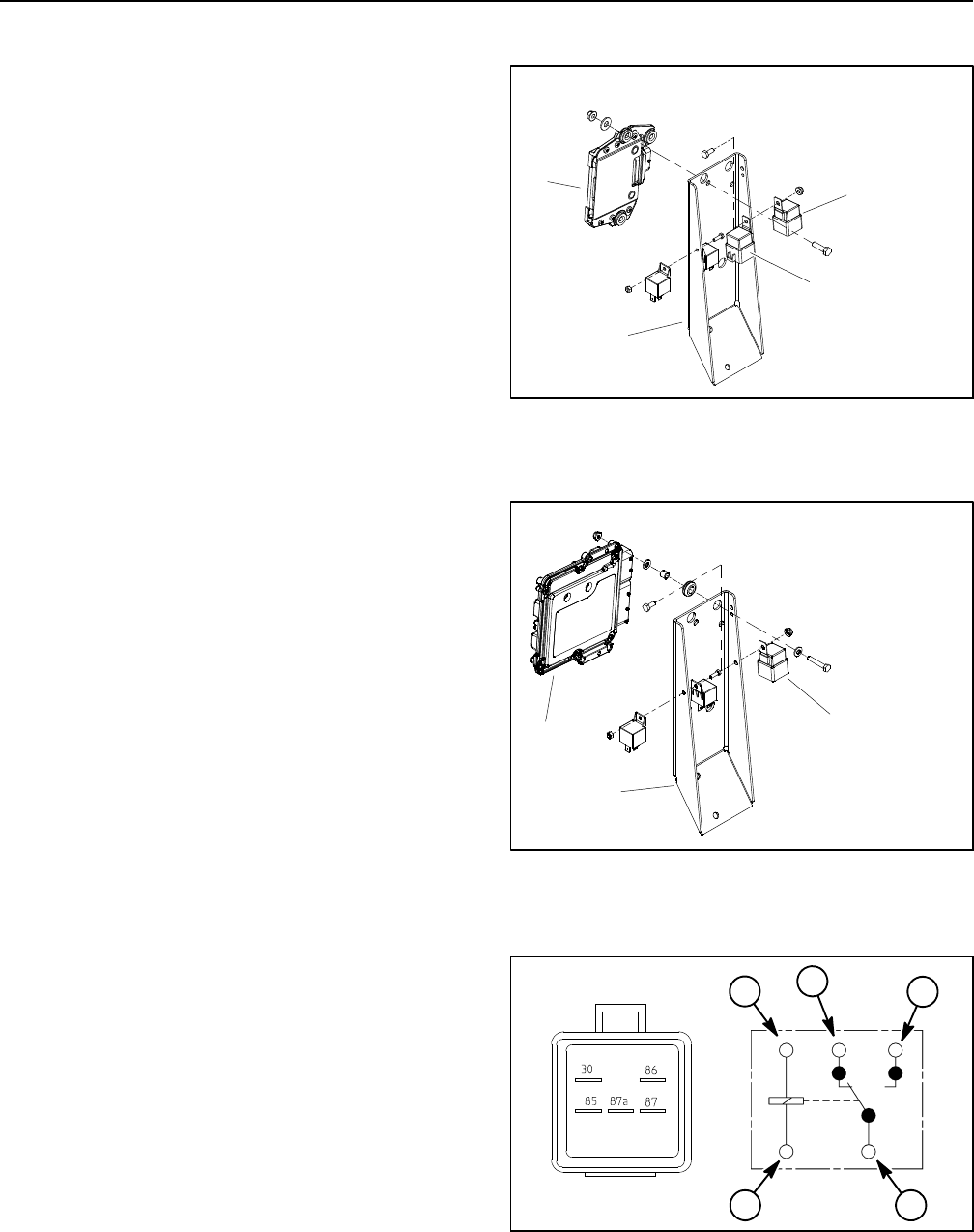
Figure 61
86
85
87A 87
30
2
1
3
4
1. Coil terminal
2. Common terminal
3. Normally closed term.
4. Normally open term.
1