


Groundsmaster 4000--D/4010--D Page 5 -- 29 Electrical System
Electrical System Quick Checks
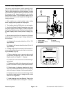
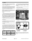
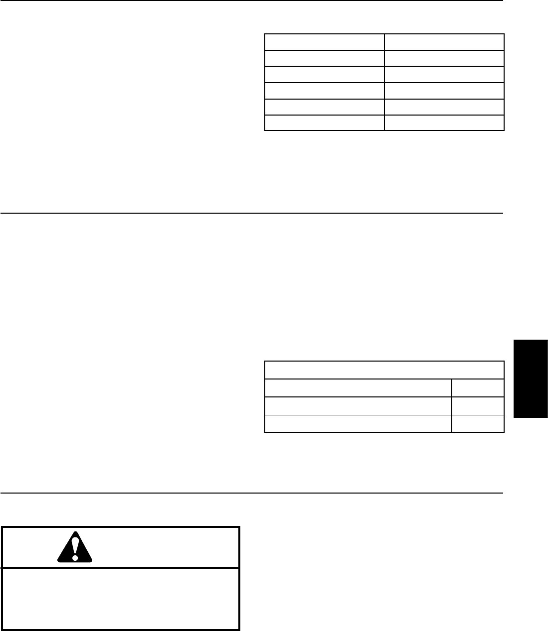
Battery Test (Open Circuit)
Use a multimeter to measure the voltage between the
battery terminals.
Set multimeter to the DC volts setting. The battery
should be at a temperature of 60
o
to 100
o
F(16
o
to
38
o
C). Theignition key should beoff andall accessories
turned off. Connect the positive (+) multimeter lead to
the positive battery post and the negative (--) multimeter
leadto thenegative battery post.The multimeterwilldis-
play battery voltage.
NOTE: This testprovides arelative condition of thebat-
tery. Load testing of the battery will provide additional
and more accurate information.
Voltage Measured
Battery Charge Level
12.68 V (or higher) Fully charged (100%)
12.45 V 75% charged
12.24 V 50% charged
12.06 V 25% charged
11.89 V 0% charged
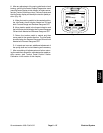
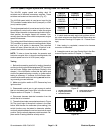
Charging System Test
This is a simple test used to determine if a charging sys-
tem is functioning. I t will tell you if the charging system
has an output, but not its capacity.
NOTE: The InfoCenter display can be used to identify
battery voltage during machine operation.
Use a digital multimeter set to DC volts. Connect the
positive (+) multimeter lead to the positive battery post
and thenegative (--) multimeterlead to the negative bat-
tery post. Keep the test leads connected to the battery
posts and record the battery voltage.
NOTE: Upon starting the engine, the battery voltage
will drop and then should increase once the engine is
running.
NOTE: Depending upon the condition of the battery
charge and battery temperature, the battery voltage will
increase at different rates as the battery charges.
Start the engine and run at high idle. Allow the battery
to charge for at least three ( 3) minutes. Record the bat-
tery voltage.
After running the engine for at least three (3) minutes,
battery voltage should be at least 0.50 volt higher than
initial battery voltage.
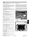
An example of a charging system that is functioning:
At least 0.50 volt over initial battery voltage.
Initial Battery Voltage = 12.30 v
Battery Voltage after 3 Minute Charge = 12.95 v
Difference =+0.65v
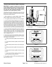
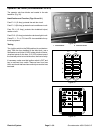
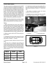
Check Operation of Interlock Switches
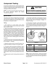
CAUTION
Do not disconnect safety switches. They are for
the operator’s protection. Checkthe operationof
the interlockswitches daily forproper operation.
Replace any malfunctioning switches before o p-
erating the machine.
Interlock switch operation is described in the Traction
Unit Operator’s Manual. Your Groundsmaster is
equipped with t wo (2) Toro Electronic Controllers (TEC)
which monitor interlock switch operation. Testing of indi-
vidual interlock switches and relays is included in the
Component Testing section of this Chapter.
NOTE: Use the InfoCenter Display when troubleshoot-
ing an electrical problem on your Groundsmaster.
Electrical
System