


Groundsmaster 4000--D/4010--D Hydraulic SystemPage 4 -- 87
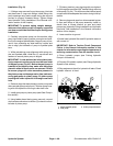
Removal (Fig. 61)
1. Park machine on a level surface, lower cutting
decks, stop engine, apply park ing brake and remove
key from the ignition switch.
2. To prevent contamination of hydraulic system during
removal, thoroughly clean exterior of pump assembly.
3. Raise and support machine to gain access to pump
assembly from the underside of machine.
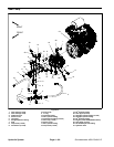
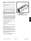
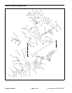
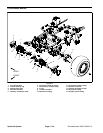
4. Label wire harness connectors that attach to the two
(2) solenoid coils on left side of piston pump (Fig. 62).
Disconnect harness connectors from solenoid coils on
piston pump.
5. Read the General Precautions for Removing and
Installing Hydraulic System Components at the begin-
ning of the Service and Repairs section of this chapter.
6. For installationpurposes, labelall hydrauliclines that
connect to gear pump and piston pump.
7. Put a drain pan below the pump assembly. Remove
hydraulic lines connected to piston and gear pump fit-
tings. Put plugs or caps on disconnected hydraulic lines
and fittings to prevent contamination of the system.
NOTE: If fuel tank is removed from the machine, the
gear pump and piston pump can be removed as a com-
plete assembly.
8. Remove gear pump from machine (see Gear Pump
in this section).
IMPORTANT: Dry weight of piston (traction) p ump
is 90 pounds (41 kg).
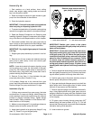
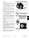
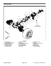
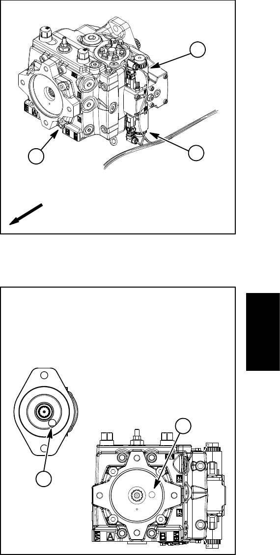
NOTE: A case drain exists in the piston (traction) pump
and a suction port is near the input shaft of the gear
pump (Fig. 63). When the gear pump is removed from
the piston pump, plug piston pump case drain hole to
prevent draining the piston pump.
9. Support the piston pump to prevent it from falling.
Remove two (2) cap screws and washers retaining
pump assembly to engine flywheel plate. Carefully pull
pump assembly from flywheel plate and lower it out of
the machine.
10.If hydraulic fittings are to be removed from piston
pump, mark fitting orientation to allow correct assembly.
Remove fittings from pump and discard O--rings.
1. Piston pump
2. Solenoid coil (forward)
3. Solenoid coil (reverse)
Figure 62
2
3
1
FRONT
1. Piston pump case drain 2. Gear pump suction port
Figure 63
after gear pump is removed.
2
1
drain and gear pump suction port
install plugs in piston pump case
To prevent draining the pumps,
Remove plugs before installing
gear pump to piston pump
Hydraulic
System