


Groundsmaster 4000--D/4010--D Hydraulic SystemPage 4 -- 121
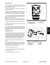
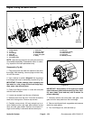
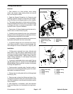
Removal (Fig. 86)
1. Park machine on a level surface, lower cutting
decks, stop engine, apply park ing brake and remove
key from the ignition switch.
2. Unlatch and raise hood.
CAUTION
The radiator and oil cooler may be hot. To avoid
possible burns, allow the engine and cooling
systems to cool before removing fan motor.
3. Read the General Precautions for Removing and
Installing Hydraulic System Components at the begin-
ning of the Service and Repairs section of this chapter.
4. Thoroughly clean three (3) hydraulic tubes at lower
radiator shroud. Disconnect hydraulic tubes and put
caps or plugs on tubes to prevent contamination. Label
disconnected hydraulic tubes for proper installation.
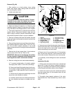
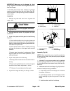
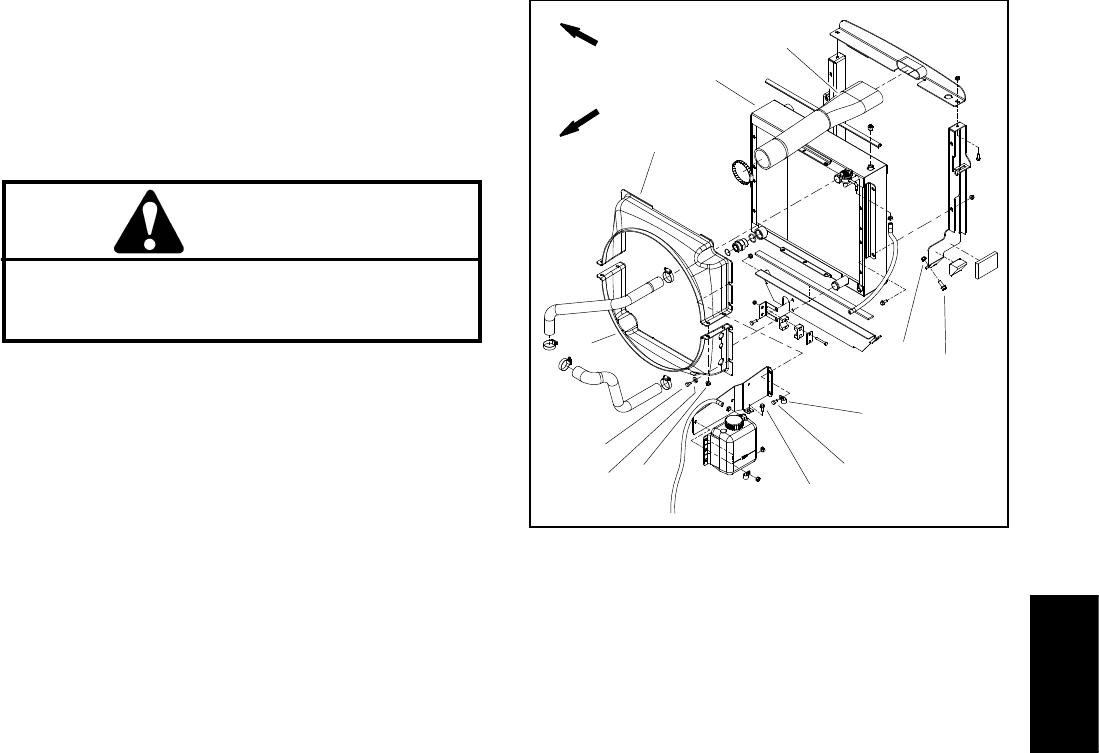
5. Remove air cleaner inlet hose and radiator shrouds
(upper and lower) toallow easier access tohydraulic fan
motor (Fig. 87).
6. Remove flangehead screws andflange nuts thatse-
cure radiator supports to frame (items 11 and 12 in Fig.
87). This will allow r adiator assembly to be moved
slightlyto easeremoval of coolingfanmotor andbracket
assembly.
7. Remove four (4) cap screws (item 11) and washers
used to secure fan to fan hub. Remove fan.
IMPORTANT: Make sure to not damage the radiator
or other machine components while loosening and
removing the fan motor a nd bracket assembly.
8. Remove cooling fan motor and bracket assembly.
A. To prevent contamination of hydraulic system,
thoroughly clean exterior of fan motor and fittings.
B. Disconnect three(3) hydraulictubesfrom fanmo-
tor. Put caps or plugs on fittings and tubes to prevent
contamination. Label hydraulic lines for proper as-
sembly.
C. Remove six (6) cap screws and flange nuts that
secure fan motor bracket to radiator.
D. Carefully remove fan motor and bracket assem-
bly from machine and place on suitable work sur-
face.
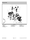
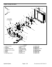
1. Radiator
2. Upperradiatorshroud
3. Lower radiator shroud
4. Screw (4 used)
5. Flange nut (4 used)
6. Cap screw (2 used)
7. Cap screw (6 used)
8. Flat washer (7 used)
9. R--clamp
10. Air cleaner inlet hose
11. Screw (4 used)
12. Flange nut (4 used)
Figure 87
3
5
6
4
7
1
2
8
9
10
11
12
FRONT
RIGHT
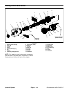
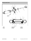
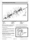
9. Removehex nut (item9) and washer(item8) that se-
cure fan hub to fanm otor.Use suitable puller tocarefully
remove fan hub from fan motor shaft. Locate and re-
trieve woodruff key from motor shaft.
10.Remove two (2) cap screws (item 15), flat washers
(item 16) and lock nuts (item 14) that secure fan motor
to fan motor bracket. Remove fan m otor from bracket.
11.If necessary, remove fittings from motor and discard
O--rings.
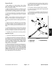
Installation (Fig. 86)
1. If fittings were removed from fan motor,lubricate and
place new O--rings onto fittings. Install and tighten fit-
tings in port openings (see Hydraulic Fitting Installation
in the General Information section of this chapter).
2. Position fan motor to fan motor bracket and secure
with cap screws (item 15), flat washers (item 16) and
lock nuts (item 14).
3. Thoroughly clean tapered surfaces of fan motor
shaft and fan hub. Place woodruff key in slot in motor
shaft.
Hydraulic
System