


Groundsmaster 4000--D/4010--D Hydraulic SystemPage 4 -- 45
Procedure for Traction Circuit Relief Pressure
Test
NOTE: Thetractionchargecircuitisdesignedtore-
place loss of hydraulic fluid from the closed loop traction
circuit.
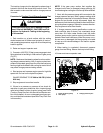
CAUTION
Prevent personal injury and/or damage to equip-
ment. Read all WARNINGS, CAUTIONS and Pre-
cautions for Hydraulic Testing at the beginning
of this section.
1. Park machine on a level surface with the cutting
decks lowered and off. Make sure hydraulic oil is at nor-
mal operating temperature, engine isoff and theparking
brake is applied.
When performing the traction circuit relief pres-
sure test, move machine to an open area, away
from people and obstructions.
CAUTION
2. Drive machine to an open area, lower cutting decks,
turn the engine off and apply the parking brake.
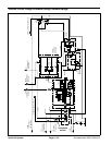
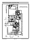
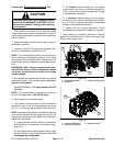
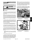
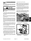
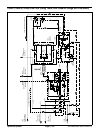
3. Connect a 10,000 PSI (700 bar) pressure gauge to
traction circuit test port for function to be checked (Fig.
28 or 29).
4. Start engine and increase engine speed to high idle
speed. Release parking brake. Make sure that HI/LOW
speed switch is in the HI (transport) position.
NOTE: If possible, turn off Smart Power
TM
by using the
InfoCenter display protected menu. Machines with TEC
software above revision level G will allow Smart
Power
TM
to be disabled fortesting. Check softwarerevi-
sion level using the InfoCenter About screen.
5. Sit on seat, apply brakesfully andslowly depress the
traction pedal in theappropriate direction(forward or re-
verse). While pushing traction pedal, look at pressure
reading on gauge:
GAUGE READING TO BE:
Forward: 4100 to 4600 PSI (283 to 317 bar)
Reverse: 4750 to 5250 PSI (328 to 362 bar)
6. Release traction pedal and stop engine. Record test
results.
7. If trac tion pressure is too low, inspect traction pump
relief valves (Fig. 28 or 29). Clean or replace relief
valves as necessary. These cartridge type valves are
factory set, and are not adjustable. If relief valves are in
good condition, traction pump or wheel motors should
be suspected of wear and inefficiency.
8. When testing is completed, disconnect pressure
gauge from test port. Secure dust cap to test fitting.
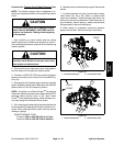
1. Forward traction port 2. Forward relief valve
Figure 28
FRONT
1
2
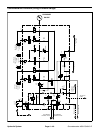
1. Reverse traction port 2. Reverse relief valve
Figure 29
FRONT
RIGHT
1
2
Hydraulic
System