


Groundsmaster 4000--D/4010--D Hydraulic SystemPage 4 -- 141
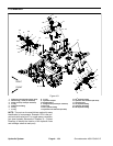
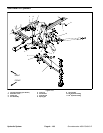
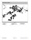
Removal (Fig. 106)
1. Park machine on a level surface, lower cutting
decks, stop engine, apply park ing brake and remove
key from the ignition switch.
2. Read the General Precautions for Removing and
Installing Hydraulic System Components at the begin-
ning of the Service and Repairs section of this chapter.
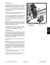
3. To prevent contamination of hydraulic system during
lift cylinder removal, thoroughly clean exterior of cylin-
der and fitting.
WARNING
Make sure that front cutting deck is fully lowered
before loosening hydraulic lines from center
deck lift cylinders. If deck is not fully lowered as
hydraulic lines are loosened, deck may drop un-
expectedly.
4. Disconnect hydraulic hose from lift cylinder.
5. Remove flange nut and flange head screw that se-
curethepin assembly(item 4)to thelift arm. Remove pin
assembly from lift arm and cylinder rod end which will
free lift cylinder from lift arm.
6. Remove one (1) cotter pin and two (2) flat washers
fromone end of the clevispin (item 8)that securesbarrel
end of lift cylinder to front frame. Pull clevis pin from
frame and cylinder barrel.
7. Remove lift cylinder from machine.
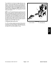
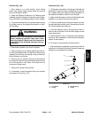
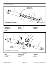
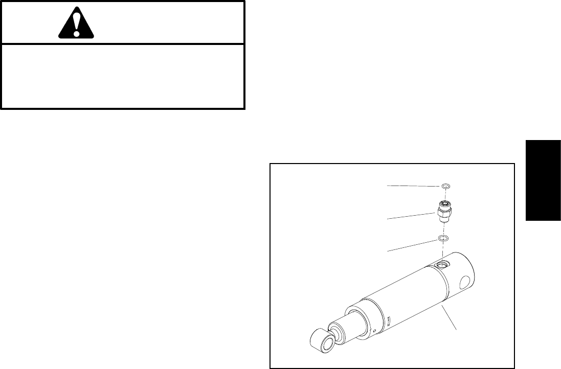
8. If necessary, remove hydraulic fitting from cylinder
and discard O--rings (Fig. 107).
Installation (Fig. 106)
1. If fitting was removed from lift cylinder, lubricate and
place new O--rings onto fitting. Install fitting into cylinder
port. Tighten fitting (see Hydraulic Fitting Installation in
the General Information section of this chapter).
2. Make surethat cotterpin andtwo (2)flat washersare
installed on one end o f the clevis pin (item 8).
3. Position cylinder barrel to frame and insert clevis pin
throughframe andcylinder barrel. Secureclevis pinwith
two (2) flat washers and cotter pin.
4. Insert pin assembly (item 4) through lift arm and cyl-
inder rod end. Secure pin to lift arm with flange nut and
flange head screw.
5. Attach hydraulic hose to lift cylinder (see Hydraulic
Hose and Tube Installation in the General Information
section of this chapter).
6. Fill reservoir with hydraulic fluid as required.
7. After assembly is completed, operate center deck lift
cylinders to verify that lift cylinders, hydraulic hoses and
fittings are not contacted by anything.
1. Lift cylinder
2. O--ring
3. Straight fitting
4. O--ring
Figure 107
1
2
3
4
Hydraulic
System