


Groundsmaster 4000--D/4010--DPage 5 -- 38Electrical System
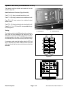
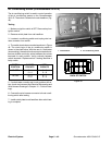
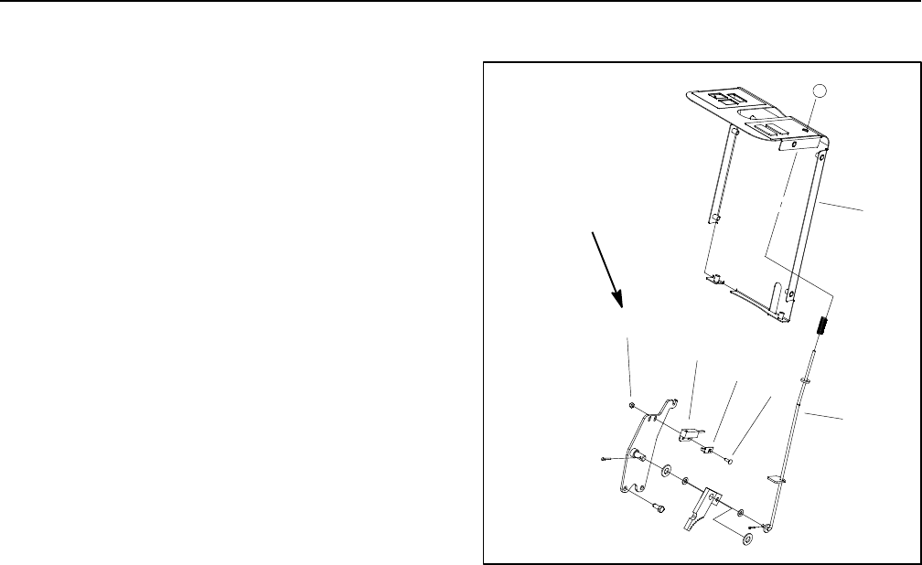
Parking Brake Switch
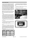
Theswitch usedfor the parking brake isa normallyopen
proximity switch that is located under the steering tower
cover (Fig. 42). The parking brake switch is an input for
the TEC controller. When the parking brake is not ap-
plied, atabon thebrake rodis positioned nearthe switch
sense zone which causes the switch to close (continu-
ity). Whenthe parkingbrakeis applied,thebrakerod tab
is positioned away from the switch allowing the switch
to be in its normal, open position (no continuity).
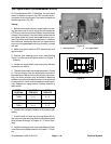
Switch Testing
1. Before disconnecting the parking brake switch for
testing, the switch and its circuit wiring should be tested
as a TEC input with the InfoCenter Display (see In-
foCenter Display in this chapter). If the InfoCenter veri-
fies that the brake switch and circuit wiring are
functioning correctly, no further switch testing is neces-
sary. If, however, the InfoCenter determines that the
brake switch and circuit wiring are not functioning cor-
rectly, proceed with test.
2. Make sure ignition switch is OFF. Remove key from
ignition switch.
3. Remove front steering tower cover (see Steering
Tower in the Service and Repairs section of Chapter 7
-- Chassis).
4. Locate parking brake switch and unplug wire har-
ness connector from switch.
5. Check the continuity of the switch by connecting a
multimeter (ohms setting) across the connector termi-
nals.
6. When the parking brake is not applied (brake rod tab
close to brake switch), there should be continuity (zero
resistance) between the switch terminals.
7. When the parking brake is applied (brake rod tab
awayfrom brake switch),there shouldbe no continuity
(infinite resistance) between the switch terminals.
8. Replace parking brake switch if necessary.
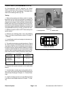
9. Correctly connect the wire harness connector to the
parking brake switch after testing is completed.
10.Install front steeringtower cover(seeSteering Tower
in the Service and Repairs section of Chapter 7 -- Chas-
sis).
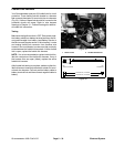
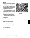
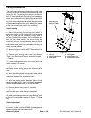
Switch Adjustment
With the parking brake not applied (brake rod tab near
the switch), there should be a 0.062” (1.6 mm) gap be-
tween the switch and the brake rod tab.
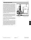
1. Lock nut
2. Parking brake switch
3. Switch plate
4. Carriage bolt
5. Parking brake rod
6. Steering tower cover
Figure 42
34 to 42 in--lb
(3.9 to 4.7 N--m)
2
3
6
1
5
4