


Groundsmaster 4000--D/4010--DHydraulic S ystem Page 4 -- 136
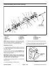
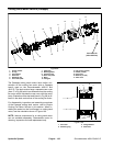
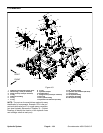
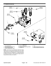
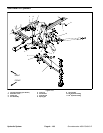
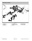
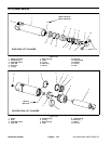
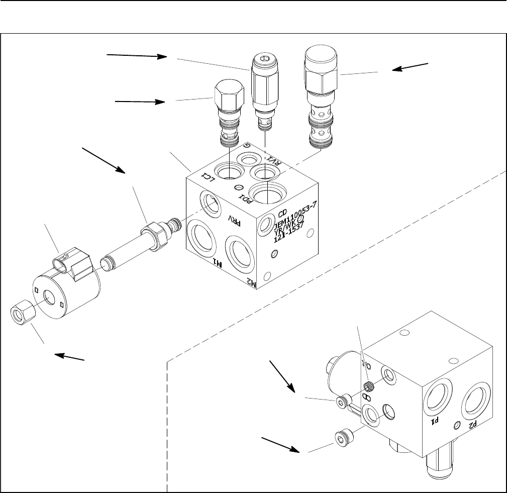
PTO Manifold Service
1. PTO manifold body
2. NWD SAE #4 plug with O--ring
3. Orifice (0.025) (port OR)
4. #6 zero leak plug with O--ring
5. Relief valve (port RV1)
6. Proportional relief valve (port PRV)
7. Solenoid coil
8. Nut
9. Logic cartridge valve (port LC1)
10. Pilot directional valve (port PD1)
Figure 103
20 ft--lb
(27 N--m)
5ft--lb
(6.7 N--m)
20 ft--lb
(27 N--m)
8
6
7
5
25 ft--lb
(34 N--m)
35 ft--lb
(47 N--m)
10
9
1
4
2
3
25 ft--lb
(34 N--m)
20 ft--lb
(27 N--m)
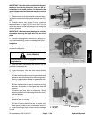
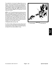
NOTE: The ports on the manifold are marked for easy
identification of components. Example: RV is the relief
valve port and P1 is the gear pump connection port (see
Hydraulic Schematic in Chapter 10 -- Foldout Drawings
to identify the function of the hydraulic lines and car-
tridge valves at each port location).