


Groundsmaster 4000--D/4010--DPage 7 -- 8Chassis
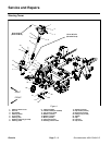
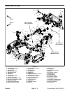
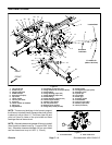
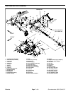
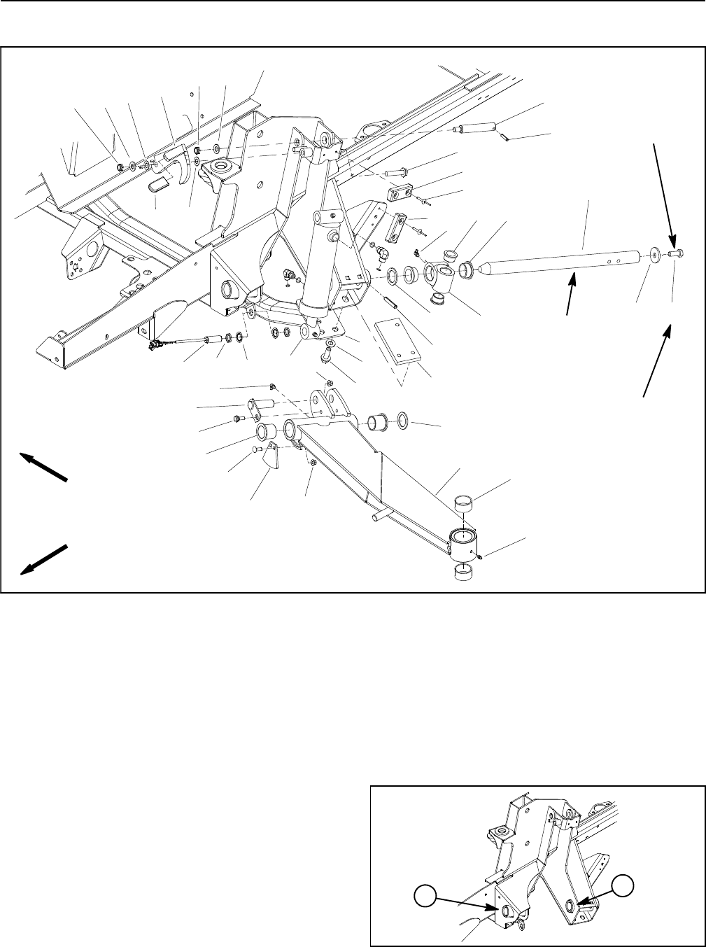
Side Deck Lift Arms
1. Lift cylinder pin
2. Slotted roll pin
3. Flange head screw
4. Rubber bumper
5. Rivet (2 per bumper)
6. Cap screw
7. Thrust washer
8. Lift arm pivot shaft
9. Pivot hub
10. Thrust washer (as needed)
11. Spring pin
12. Tapped block
13. Flat washer (5 used per side)
14. Flange head screw (3 used per block)
15. Grease fitting
16. Flange bushing (2 per hub)
17. Flange bushing (2 per hub)
18. Grease fitting
19. Flange bushing (2 per lift arm)
20. Jam n ut (2 per switch)
21. Washer (2 p er switch)
22. Lift arm (LH shown)
23. Bushing (2 per lift arm)
24. Flange nut (3 used per side)
25. Sensing plate
26. Carriage screw (2 per plate)
27. Shoulder screw
28. Cylinder pin
29. Lift cylinder
30. Plastic grip
31. Proximity switch
32. Crossmember
33. Lock nut (2 per side)
34. Washer (2 p er latch)
35. Latch (LH shown)
Figure 6
FRONT
RIGHT
Antiseize
Lubricant
Loctite #242
77 to 96 ft--lb
(105 to 130 N--m)
2
3
6
8
9
10
11
13
1
5
7
12
14
15
16
17
18
19
20
4
21
22
23
24
25
26
27
28
29
31
32
33
34
35
4
10
34
33
13
13
24
30
15
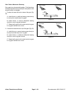
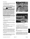
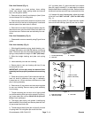
NOTE: There are not bushings in the frame to support
the lift arm pivot shaft (item 8) because the shaft is fixed
in place by a roll pin (item 11). The lift arm (item 22) and
pivot hub (item 9) rotate on the pivot shaft and have
bushings that can be serviced.
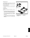
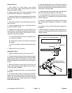
NOTE: Allowableclearancebetween lift arm pivotshaft
(item8) andfrontframe bore(Fig. 7)isup to0.025”(0.64
mm). Allowable clearance between lift arm pivot shaft
andrearframeboreisupto0.070”(1.78mm).
1. Front frame bore 2. Rear frame bore
Figure 7
2
1