


Groundsmaster 4000--D/4010--D Page 7 -- 19 Chassis
IMPORTANT: A properly installed and calibrated
traction pedal position sensor is critical to accurate
traction system response and for reliable sensor
life. Use care when removing, installing and cali-
brating t he traction pedal position sensor.
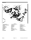
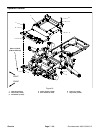
Disassembly (Fig. 17)
1. Park machine on a level surface, lower cutting
decks, stop engine, apply park ing brake and remove
key from the ignition switch.
2. Remove front steering tower cover (see Steering
Tower in this section).
3. Disconnect machine wire harness connector from
position sensor (item 28) on traction pedal.
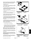
4. If the tractionpedalis tobe removed fromthetraction
pedalshaft,use amarkeror paint penon pedal andshaft
to identify location of pedal for assembly purposes.
5. Disassemble tractionpedal asneeded usingFigures
17 and 18 as guides. When removing roll pin (item 10 in
Fig. 17), make sure to support shaft to prevent compo-
nent damage.
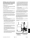
Assembly (Fig. 17)
1. Assemble traction pedal using Figures 17 and 18 as
guides noting the following items:
A. Apply grease to both the OD and ID of the spring
retainer (item 35 in Fig. 17) before installation. Take
caretonotget greaseonthreads ofspring shaft(item
32 in Fig. 17) or lock nut (item 37 in Fig. 1 7).
B. If lock nut (item 37 in Fig. 17) was removed, tight-
en nut until washer (item 36 in Fig. 17) does not ro-
tate.
C. If traction pedal shaft (item 9 in Fig. 17) was re-
moved, apply grease to the shaft areas that will be
inside the bearings after assembly.
D. Use a press to install roll pin (item 10 in Fig. 17).
DO NOT damage flange mount bearing ( item 17 in
Fig. 17) or cover plate (item 18 in Fig. 17) when in-
stalling roll pin. Also, take care to not distort roll pin
during assembly.
E. Make sure that roll pin (item 10 in Fig. 17) is fully
inside the butterfly groove of the shim plate (item 20
in Fig. 17). The roll pin should not contact the shim
plate throughout the operating range.
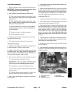
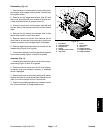
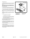
F. To install the traction pedal position sensor (item
28 in Fig. 17), press and holdthe traction pedal in the
reverse direction slightly. Align the slot on the end of
the pedal shaft with the slot in the position sensor.
Slideposition sensoronto screwsand releasepedal.
Hold position sensor in position while installing cap-
tureplate (item29 inFig. 17) andlock nuts(item25 in
Fig. 17).
G. Torque screws (item 31 in Fig. 17) from 13 to 17
in--lb (1.5 to 1.9 N--m).
H. Leave the hex nut (item 7 in Fig. 17) loose so that
the position sensor can be calibrated.
2. After traction pedal assembly, make sure that there
is no binding in pedal movement and also that pedal re-
turns to the centered position when released. Correct
any sticking or binding before machine operation.
3. Plug machine wire harness connector into traction
pedal position sensor (item 28 in Fig. 17).
4. Afterassembly ofthe tractionpedal, adjustand calib-
rate the traction pedal and position sensor using the In-
foCenter display (see Traction Pedal Adjustment and
Traction Pedal Calibration in the Adjustments section of
Chapter 5 -- Electrical System).
5. Make sure thathex nut (item 7 inFig. 17) istightened
after position sensor adjustment.
6. Install front steeringtower cover(see Steering Tower
in this section).
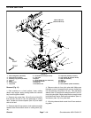
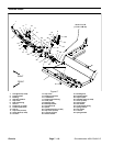
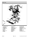
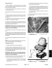
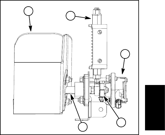
1. Traction pedal
2. Pedal position sensor
3. Traction pedal shaft
4. Clamp block (2 used)
5. Spring shaft assembly
Figure 18
1
2
4
3
5
Chassis