


Groundsmaster 4000--D/4010--D Hydraulic SystemPage 4 -- 81
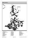
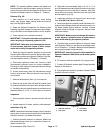
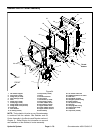
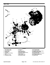
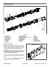
Removal (Fig. 55)
1. Park machine on a level surface, lower cutting
decks, stop engine, apply park ing brake and remove
key from the ignition switch.
2. Raise and support machine to gain access to gear
pump from the underside of the machine.
3. Drain the hydraulic reservoir.
IMPORTANT: Follow all localcodes and regulations
when recycling or disposing hydraulic fluid.
4. To prevent contamination of hydraulic system during
removal, thoroughly clean exterior of pump and fittings.
5. Read the General Precautions for Removing and
Installing Hydraulic System Components at the begin-
ning of the Service and Repairs section of this chapter.
6. Disconnect hydraulic lines from gear pump and put
caps or plugs on open hydraulic lines and fittings. Label
disconnected hydraulic lines for proper installation.
IMPORTANT: Dryweight of gear pump is 23 pounds
(10.2 kg).
7. Support gear pump assembly to prevent it from fal-
ling.
8. Remove two (2) cap screws and washers securing
gear pump to piston pump. Lower and remove gear
pump from machine.
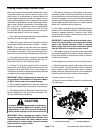
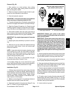
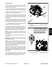
NOTE: A case drain exists in the piston (traction) pump
and a suction port is near the input shaft of the gear
pump (Fig. 56). When the gear pump is removed from
the piston pump, plug piston pump case drain hole to
prevent draining the piston pump.
9. Remove O--ring (item 11) from between the gear
pump and piston pump. Discard O--ring.
10.If hydraulic fittings are to be removed from gear
pump, mark fitting orientation to allow correct assembly.
Remove fittings from pump and discard O--rings.
Installation (Fig. 55)
1. If fittings were removed from gear pump, lubricate
and place new O--rings onto fittings. Install fittings into
pump openings using marks made during the removal
process to properly orientate fittings. Tighten fittings
(see Hydraulic Fitting Installation in the General Infor-
mation section of t his chapter).
2. Make sure mounting and O--ring sealing surfaces on
the gear pump and piston pump are clean.
3. Apply clean hydraulic oil to gear p ump flange O--ring
(item 11). Place O--ring on the gear pump.
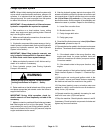
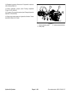
1. Piston pump case drain 2. Gear pump suction port
Figure 56
Remove plugs before installing
gear pump to piston pump
2
1
IMPORTANT: Position gear pump to the piston
(traction)pump sothatthe gearpumpinlet (suction)
ports are facing down.
IMPORTANT: A case drain exists in the piston (trac-
tion) pump and a suction port is near the input shaft
of the gear pump (Fig. 56). Before the gear pump is
installed to the piston pump, make sure that plugs
placed in either of these ports are removed. Failure
to remove plugs will cause excessive pressure in
the pistonpump and damage seals. Also, before se-
curing gear pump to piston pump, fill piston pump
housing with clean hydraulic oil through case drain
hole.
4. Remove plugs that were placed in piston pump case
drainand gearpump suction port.Fill pistonpump hous-
ing with clean hydraulic oil through case drain hole.
5. Position gear pump to the piston (traction) pump so
that the pump inlet ports are facing down.
6. Align gear teeth and slide gear pump input shaft into
piston pump shaft. Secure gear pump to piston pump
with two (2) cap screws and flat washers.
7. Remove caps and plugs from hydraulic lines and fit-
tings. Using labels placed during gear pump removal,
properly install lines to gear pump (see Hydraulic Hose
and Tube Installation in the General Information section
of this chapter).
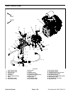
8. Fill piston pump housing through case drain (90
o
barbed fitting) with new hydraulic oil (Fig. 57). This will
ensure that internal pump components have adequate
lubrication during initial operation.
9. Lower machine to ground.
Hydraulic
System