


Groundsmaster 4000--D/4010--DPage 5 -- 36Electrical System
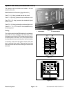
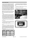
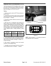
Cruise Control Switch
The cruisecontrol switch is used as an inputfor the TEC
controllerto maintain ground speedwhen engaged.The
cruise control function is enabled when the switch is in
the ON (center) position. Pressing the front of theswitch
to the momentary position sets the desired ground
speed. The cruise control function is disengaged when
the rear of the cruise control switch is depressed. On
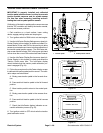
machine with serial numbers below 314000000, the
cruise control switch is located on the operator side of
the console arm (as shown in Fig. 39). On machine with
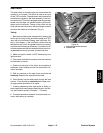
serial numbers above 314000000, the cruise control
switch is located on the outside the console arm.
NOTE: Thecruisecontrolfunctioncanalsobedisen-
gaged if either brake pedal is pressed or if the traction
pedal is pressed and held in the reverse direction.
Testing
1. Before disconnecting the cruise control switch for
testing, the switch and its circuit wiring should be tested
as a TEC input with the InfoCenter Display (see In-
foCenter Display in this chapter). If the InfoCenter Dis-
playverifies that switchand circuitwiring arefunctioning
correctly, no further switch testing is necessary. If, how-
ever, the Display determines that the switch and circuit
wiring are not functioning correctly, p roceed with test.
2. Make sure ignition switch is OFF. Remove key from
ignition switch.
3. Disassemble control armto gain accessto the cruise
controlswitch(seeControlArmintheServiceandRe-
pairs section of Chapter 7 -- Chassis).
4. Disconnect harness electrical connector from the
switch.
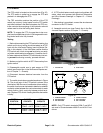
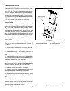
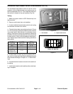
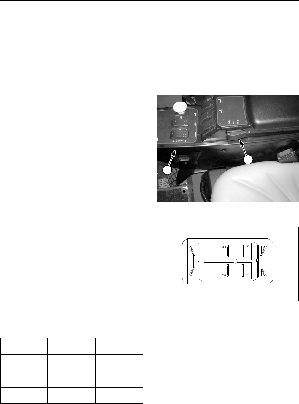
5. With the use of a m ultimeter (ohms setting), the
switch functions may be te sted to determine whether
continuity exists between the various terminals for each
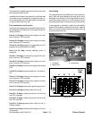
position. The switch terminals are marked as shown in
Figure 40. The circuitry of the cruise control switch is
shown in the chart below. Verify continuity between
switch terminals.
SWITCH
POSITION
CLOSED
CIRCUITS
OPEN
CIRCUITS
CRUISE
DISENGAGE
NONE ALL
CRUISE ON
(CENTER)
2+3 5+6
SPEED SET
(MOMENTARY)
2+3
5+6
NONE
6. If switch tests correctly and circuit problem still ex-
ists, check wire harness(see Electrical Schematics and
Wire Harness Drawings in Chapter 10 -- Foldout Draw-
ings).
7. After testing is completed, connect wire harness
connector to the cruise control switch.
8. Assemble control arm (see Control Arm in the Ser-
vice and Repairs section of Chapter 7 -- Chassis).
1. Control arm 2. Cruise control switch
Figure 39
1
2
Figure 40
BACK OF SWITCH