


Groundsmaster 4000--D/4010--DPage 5 -- 60Electrical System
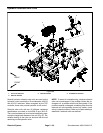
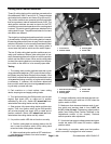
Cutting Deck Position Switches
Three (3) cutting deck position switches are usedon the
Groundsmaster 4000--D and 4010--D. These switches
are located on the traction unit frame (Figs. 80 and 81).
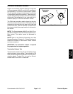
The position switches are powered proximity switches
that incorporate an internal reed switch and a LED. T he
deck position switches are used as inputs for the TEC
controller toprevent deck operation when acutting deck
is raised. The switch sensing plates are attached to the
cutting decklift arms. The positionswitches for front and
side decks are different.
The single front cutting deck position switch is a normal-
ly closed switch. When the front cutting deck is lowered,
the sensing plateon thelift armis awayfrom theposition
switch sothe switch is inits normally closed state. When
the front cutting deck is raised, the sensing plate is
movednearthepositionswitchandtheswitchopens.
The two (2) side cutting deck position switches are nor-
mally open switches. When a side cutting deck is low-
ered, the sensingplate onthe liftarm is nearthe position
switch and the switch closes. When a side cutting deck
israised, thesensingplateis movedaway from theposi-
tion switch so the switch is in its normally open state.
Testing
1. The cutting deck position switches and their circuit
wiring should be tested as aTEC input with the InfoCen-
terDisplay (seeInfoCenter Displayin thischapter).If the
InfoCenter verifies that the position s witches and circuit
wiring are functioning correctly, no further switch testing
is necessary. If, however, the InfoCenter determines
that a position switch and circuit wiring are not function-
ing correctly, proceed with test.
2. Park machine on a level surface, lower cutting
decks, stop engine and apply parking brake.
3. Turn ignition switch to the RUN position (do not start
engine) and check LED on cable end of position
switches (Fig. 80 or 81). Switch LED should be illumi-
nated when the cutting decks are fully lowered.
4. Start engine, fully raise cutting decks and then stop
engine. Then, turn ignition switch to the RUN position
(do not start engine) and check LED on cable end of
position switches. Switch LED should not be illumi-
nated when the cutting decks are fully raised.
5. If a position switch LED did not function correctly:
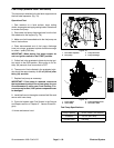
A. Position cutting deck so sensing plate on the lift
arm is near the position switch (front cutting deck
raised and side cutting decks lowered).
B. Make sure that ignition switch isOFF and discon-
nect the switch connector from wire harness.
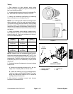
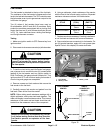
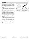
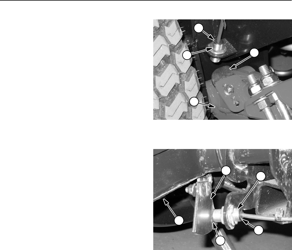
1. Front lift arm
2. Position switch
3. Sensing plate
4. Switch LED
Figure 80
3
1
2
4
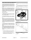
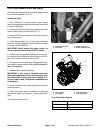
1. Side lift arm (RH shown)
2. Position switch
3. Sensing plate
4. Switch LED
5. Clearance
Figure 81
3
1
2
5
4
C. Using a multimeter, verify that wire harness con-
nector terminal for pink wire has 12 VDC when the
ignition switch is RUN.
D. Make sure that clearance between end of posi-
tion switch and sensing plate is from 0.070” to
0.130” (1.8 to 3.3 mm).Ifnecessary,adjustposition
switch (see Cutting Deck Position Switches in the
Adjustments section of this chapter). Recheck
switch operation after adjustment.
E. Ifpink wirehas systemvoltagepresent andgap is
correct but switch LED does not function, replace
position switch.
6. After testing is complete, make sure that position
switch connector is plugged into wire harness.