


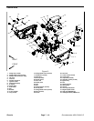
Groundsmaster 4000--D/4010--D Page 7 -- 9 Chassis
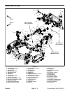
Removal (Fig. 6)
1. Park machine on a level surface, lower cutting
decks, stop engine, apply park ing brake and remove
key from the ignition switch.
2. Remove side deck from lift arm (see Side Cutting
Deck Removal in Chapter 8 -- Cutting Decks).
3. Remove sidedeck rear arm assemblyfrom pivoth ub
(see Side Deck Rear Arm Assembly Removal in this
section).
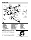
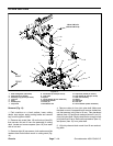
4. Remove lift cylinder pin (item 28)that secures lift cyl-
inder to lift arm.
5. Drive out slotted roll pin (item 11) that retains lift arm
pivot shaft. Discard roll pin.
6. Support lift arm and pull lift arm pivot shaft from lift
armand frame.Locateand removethrustwashers (item
10) during pivot shaft removal. Note location of thrust
washers for assembly purposes.
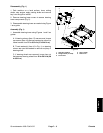
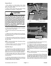
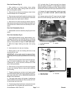
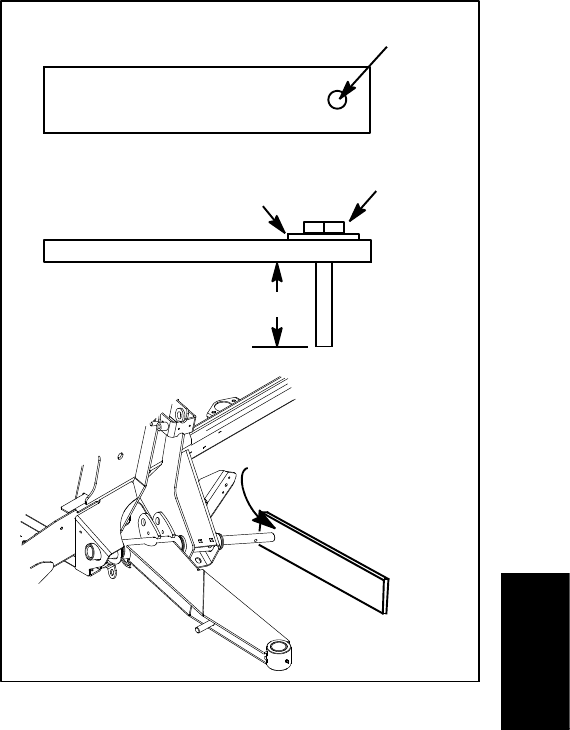
A. If pivot shaft is difficult to remove, fabricate a pull-
er as shown in Figure 8.
B. Attach puller to end of pivot shaft using bolt and
flat washer.
C. Drivepivot shaftfromlift arm andframe withham-
mer.
7. Remove lift arm from machine.
Installation (Fig. 6)
1. Apply anti--s eize lubricant to lift arm pivot shaft.
2. Positionlift armto framewith thrustwashers properly
placed (Fig. 6). Make sure that there is a thrust washer
placed between the rear of the lift arm and frame. Addi-
tional thrust washers can be used to remove end play of
lift arm.
3. Slide pivot shaft into frame and lift arm until roll pin
holes in shaft and frame align. Make sure that lift arm
pivots freely after installation.
4. Install new slotted roll pin (item 11) to secure lift arm
pivot shaft.
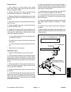
5. If pivot hub (item 9) was removed from pivot shaft,
slide pivot hub onto shaft.Apply Loctite #242(or equiva-
lent) to cap screw threads and secure pivot hub with
washer and cap screw. Torque cap screw from 77 to 96
ft--lb (105 to 130 N--m).
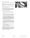
6. Align lift cylinder with lift arm. Secure lift cylinder to
lift arm with lift cylinder pin (item 28). After lift cylinder is
secured, makesure thatupper hydraulicfitting onlift cyl-
inder does not contact frame.
7. Install side deck rear arm assembly (see Side Deck
Rear Arm Assembly Installation in this section).
8. If sensing plate (item 25) was removed from lift arm,
secure plate so it is rotated as far as possible toward
center of machine.
9. Positionand install side cuttingdeck tomachine (see
Side Cutting Deck Installation in Chapter 8 -- Cutting
Decks).
10.Lubricate lift arm grease fittings after assembly is
complete.
11.After assembly iscompleted, raiseand lower thecut-
tingdeck toverify thathydraulichoses andfittings donot
contact anything.
Figure 8
3” x 12” (3/8” to 1/2” thick) plate steel
9/16” hole
1/2” -- 13 UNC bolt
Flat washer
1” to 1 1/8”
Use hammer to drive
pivot shaft from lift arm
Chassis