


5 - 12
92B/96B/99B/105B
Users Manual
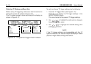
TRIGGERING
Trigger Basics
Triggering tells the ScopeMeter test tool when to begin
displaying the waveform. You can select which input signal
should be used as the source, on which edge this should
occur, and at what waveform level it should occur. Finally,
you can tell the test tool to delay the waveform to be
displayed with a specified time delay, number of cycles, or
number of events.
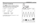
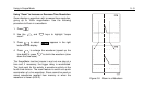
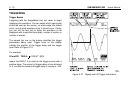
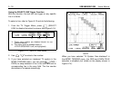
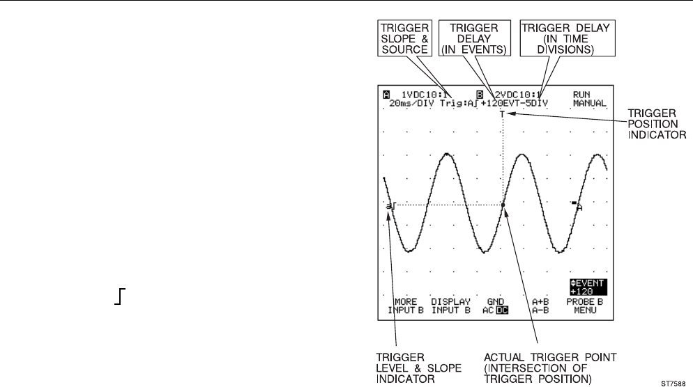
The second top row on the display identifies the trigger
parameters being used. Trigger icons on the display
indicate the position of the trigger delay and the trigger
level. Refer to Figure 5-10.
For example,
20 ms/DIV TRIG:A
+120EVT -5DIV
means that INPUT A is used as the trigger source with a
positive slope. The amount of trigger delay in time divisions
is -5, and that the amount of trigger delay in events is +120.
Figure 5-10. Display with All Trigger Information