


1 - 8 92B/96B/99B/105B Users Manual
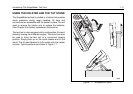
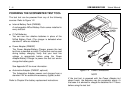
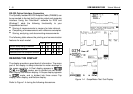
RS-232 Optical Interface Connection
The Optically Isolated RS-232 Adapter/Cable (PM9080) can
be connected to the test tool for printer output and computer
interface. Using the FlukeView software for DOS and
Windows adds the following functionality to your
ScopeMeter test tool:
•
Storing of measurements in memory for later retrieval.
•
Comparing of measurements with reference examples.
•
Storing, analyzing, and documenting measurements.
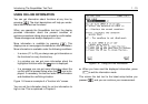
The following table shows the printing and communication
features for each model:
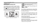
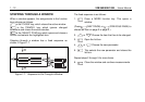
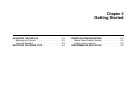
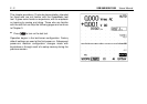
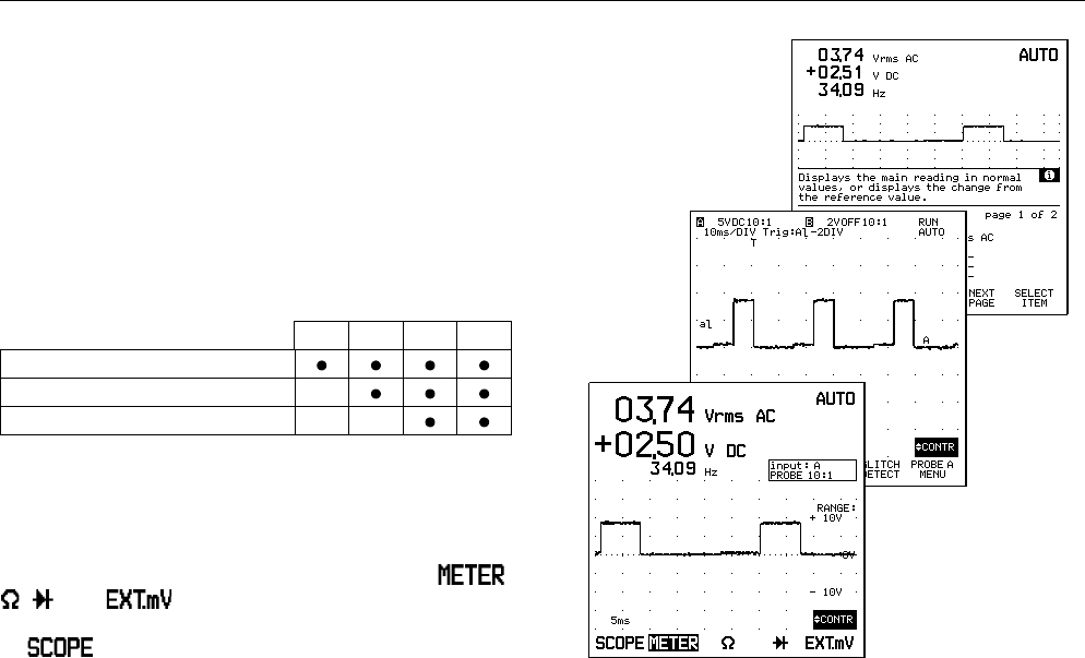
READING THE DISPLAY
The display provides a great deal of information. The major
part of the display is always devoted to meter readings or
the scope waveform. A Dual display appears in ,
, , and modes, and is divided into two areas:
Main display and Bottom display. A Scope display appears
in mode, and is divided into three areas: Top
display, Main display, and Bottom display.
Refer to Figure 1-4 during the following discussions.
Figure 1-4. ScopeMeter Test Tool Display
92B 96B 99B 105B
Screen dump using FlukeView
Direct output to printer
Remote control via computer software