


Introducing The ScopeMeter Test Tool 1 - 7
LOOKING AT ALL
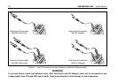
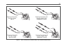
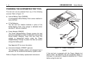
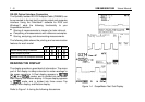
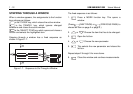
MEASUREMENT CONNECTIONS
The ScopeMeter test tool provides four signal connection
points: two safety BNC jack inputs (red INPUT A and grey
INPUT B) and two safety 4-mm banana jack inputs (COM
and
Ω
EXT.mV). This arrangement is shown in Figure
1-3. All connections are positioned within a protective recess
at the top of the instrument. The banana jacks are also used
as Waveform Generator Output.
Figure 1-3. Measurement Connections
In mode, you can use the red INPUT A BNC jack
and the grey INPUT B BNC jack as input.
In mode, only the red INPUT A BNC jack is used
as input.
In , , and modes, use the red and black 4-mm
banana jacks.
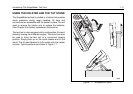
For low frequency measurements (up to about 2 MHz),
ground can be connected to the black 4-mm banana jack.
For higher frequencies you must use the HF Adapter or
Mini Testhook on the probe.
The red 4-mm banana jack also serves as an input
connection for an external trigger in Scope mode or as an
output connection for the waveform generator. This
waveform generator can provide voltage or current output.
Common Ground, Inputs A B
The test tool uses a three-lead connection system for dual
input, isolated (electrically floating) measurements.
Input/Output Terminal Ratings
Maximum voltage ratings are defined near the related
terminal. Refer to the Specifications in Appendix 10A for
complete terminal rating information.
92B 96B