


User Maintenance 8 - 5
REPLACING FUSES
Since the test tool uses electronically protected inputs, no
fuses are required.
CALIBRATING THE PROBES
The following procedures describe dc calibration and ac
adjustment for the 10:1 probe used on INPUT A (red scope
probe) and INPUT B (grey scope probe).
NOTE
To meet full user specifications, use the 10:1 probes only
with the inputs on which they have been calibrated.
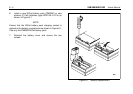
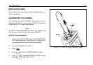
INPUT A Probe Calibration
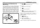
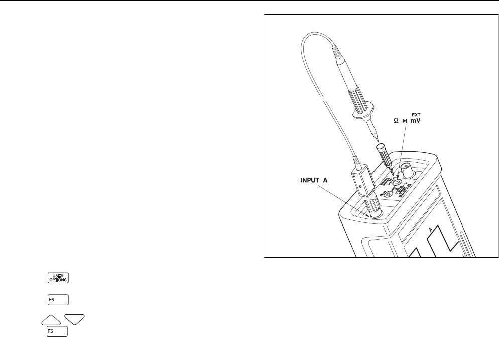
1. Connect the INPUT A BNC input to the GENERATOR
OUT red banana jack. See Figure 8-2. Use the red
scope probe and the red 4-mm banana adapter.
2. Turn the ScopeMeter test tool on.
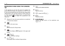
3. Press .
4. Press to open the PROBES MENU window.
5. Use to highlight PROBE on INPUT A, and
press . This opens the list box.
Figure 8-2. INPUT A Probe Calibration Setup