


5 - 4
92B/96B/99B/105B
Users Manual
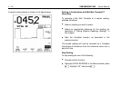
MAKING AN EASY SETUP
Continuous Auto Set automatically selects the optimum
settings for connected input signals and keeps track of any
variation of the signal. Start Continuous Auto Set by
pressing . For most signals, the ScopeMeter test tool
will automatically set inputs, amplitudes, time base setting,
and triggering for an optimum display.
Pressing sets the following:
•
INPUT A and/or INPUT B is switched on depending on
signal input. All other waveform displays are switched off.
•
Between two and five periods of the waveform with the
lowest frequency are displayed.
•
The attenuation per input is set so that the waveform
occupies about four vertical divisions.
•
The trigger source is chosen as the input signal with the
lowest frequency.
If no triggerable waveform is found when you press ,
approximate settings are used. If the input signal
subsequently changes, the test tool readjusts itself; you will
always have a meaningful picture on the display.
Continuous Auto Set can be configured through the
Menu. Refer to Chapter 6 for a complete description.
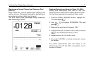
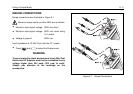
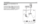
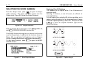
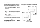
CONTROLLING INPUTS A AND B
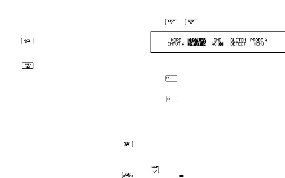
Press or to open the input settings menu.
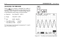
Figure 5-2. Input A Menu
Selecting the Input
Press on the appropriate input to turn it on and off.
Selecting the Input Coupling
Press on the appropriate input to select the input
signal coupling. The selection is shown in the upper line of
the top display.
AC
-coupling allows for reading ac voltages
above 40 Hz only.
DC
-coupling allows for reading ac and
dc voltages.
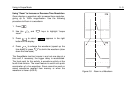
The
GND
selection disconnects the input signal and
displays the ground or zero level as a horizontal line.
Ground provides a useful tool for setting up the display to
show a high dc level or voltage spike. For example, if you
anticipate a high positive dc level, select
GND
and press
to move the ground level lower on the display. A small
marker box ( ) on the right side of the display identifies the
ground level.