


Getting Started
Getting Started
1Ć8
NOTE
Some DTE devices may have female connectors. Also, the RSĆ232
ports of personal computers may be configured as DCE or DTE
devices, with either a 25Ćpin or a 9Ćpin connector. Refer to the
documentation that accompanies your computer or terminal to
determine if it is a DTE or a DCE device.
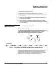
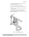
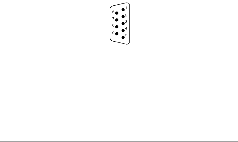
The oscilloscope is a DTE device. A 9Ćpin DĆtype shell RSĆ232 connector is
located on the rear panel. In standard usage, a male connector appears on
DTE devices, and a female connector appears on DCE devices. A straightĆ
through femaleĆtoĆmale cable of less than 50 feet is typically used for local
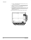
DTEĆtoĆDCE connection. Figure 1Ć10 on page 1Ć8 shows the oscilloscope
9Ćpin connector with its pin number assignments. When connecting the
oscilloscope to another RSĆ232 device consider these suggestions:
H Many devices require a constant high signal on one or more input pins
H Do not connect the output line of one DTE device to the output line of the
other.
H Ensure that the signal ground of the oscilloscope is connected to the
signal ground of the external device
H Ensure that the chassis ground of the oscilloscope is connected to the
chassis ground of the external device
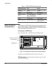
2
9ĆPIN DĆSHELL
Receive Data (RxD)
(input)
3 Transmit Data (TxD) (output)
4 Data Terminal Ready (DTR) (output)
5 Signal Ground (GND)
8 Clear to Send (CTS) (input)
1 No Connection
6 Data Set Ready (DSR) (input)
7 Request to Send (RTS) (output)
9 No Connection
Figure 1Ć10:ăPin Assignments of the RSĆ232 Connector
In terms of the connector and the way the oscilloscope uses the signal lines,
the oscilloscope behaves just like a PC/AT COM port. Table 1Ć2 lists cables
you can use to connect the oscilloscope to other devices.