


3 - Configuration
44
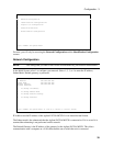
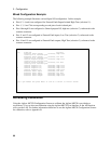
Mixed Configuration Example
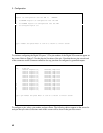
The following example illustrates a mixed digital I/O configuration. In this example,
♦ Pins 0, 2, 4, and 6 are configured for External Fault Output Isolated High True (selection 11).
♦ Pins 1, 3, 5 and 7 the corresponding second pins of each isolated pair.
♦ Pins 8 through 10 are configured as General purpose I/O, high true (selection 7), referenced to the
common connector.
♦ Pins 11 and 12 are configured as External Fault inputs, Low True (selection 2), referenced to the
common connector.
♦ Pins 14 and 15 are configured as External Fault outputs, High True (selection 3), referenced to the
common connector.
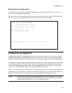
Accessing Calibration
Using the Agilent MCCD Configuration Screens to calibrate the Agilent MCCD is provided as a
convenience. You can also run calibration using the Agilent MCCD User Interface or the API function
calls over the LAN. For further information about how to use the Agilent MCCD Configuration Screens
for calibration, refer to Appendix B.
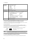
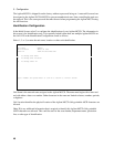
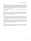
Digital I/O Configuration
Pin, Function Polarity
0 External Fault Output, Isolated, High True
1 second pin of isolated pair
2 External Fault Output, Isolated, Low True
3 second pin of isolated pair
4 General Purpose Output, Isolated, High True
5 second pin of isolated pair
6 General Purpose Output, Isolated, Low True
7 second pin of isolated pair
8 General Purpose I/O, Grounded, High True
9 General Purpose I/O, Grounded, High True
10 General Purpose I/O, Grounded, High True
11 General Purpose I/O, Grounded, High True
12 External Fault Input Grounded, Low True
13 External Fault Input Grounded, Low True
14 External Fault Output Grounded, High True
15 External Fault Output Grounded, High True
Type a pin number and press Enter or ctrl-G to return to initial screen