


2 - Installation
32
Isolated Output
When outputs are configured for optically isolated mode, they are open-collector
outputs capable of sinking 1.6mA at 0.4V, and can be used up to 24V. Adjacent pin
pairs starting with pin 0 are the plus and minus output of an optical isolator. This
allows for up to 8 isolated outputs, on adjacent pin pairs 0-1, 2-3, 4-5 etc. Because
these are dedicated pairs, pins 1 and 2 cannot be combined as an isolated output.
Special Functions
External Fault
Input
When true, this signal stops the cell forming sequence due to an external fault
condition. It also sets the external fault output signal true. This signal can be
connected to a sensor such as a fire detector. It can also be connected to the
external fault output of another Agilent MCCD so that it can respond to a fault in
another mainframe.
External Fault
Output
This signal is asserted true when an external fault occurs. It can be connected to
external equipment such as a fire alarm. It can also be connected to the external
fault input of another mainframe so that a fault in one mainframe can shut down
other mainframes. A cfProtectClear command clears this signal.
External Interlock
When true, this signal stops the cell forming sequence, but because the stop was not
due to a fault condition, it does not set the external fault output signal true. This
level-sensitive signal can be connected to an external stop or pause switch to allow
an operator or mechanical device to stop a cell forming sequence. When the signal
is removed, the sequence continues.
External Trigger
This external trigger input is used to start the cell forming sequence.
Power Fail
Depending on how the system is configured, when true, this input signal will cause
the Agilent MCCD to perform a shutdown, at which time it saves its state for a later
restart. A power fail output signal is also available to indicate when the shutdown
state has been saved.
Wiring Guidelines
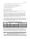
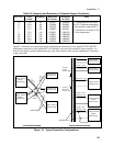
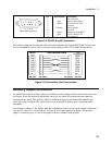
Connection for the 16 digital I/O signals are through two 10-pin Phoenix/Weidmuller style connectors.
The connectors have screw terminals for making wire connections and are detachable. Digital I/O lines 0
through 7 are on connector 1; digital I/O lines 8 through 15 are on connector 2. There are two common
terminals on each connector for ground or the return connection.
7 6 5 4 3 2 1 0
⊥
⊥
⊥⊥
8
10
11
12
1314
15
9
Figure 2-2. Digital I/O Connections
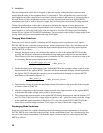
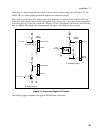
The following figure illustrates the internal circuits of the digital I/O connector. When used as a digital in
put (A), the external circuit connected to the digital input pin can be TTL, AS, CMOS, HC, or a simple
switch that connects the digital input to the common terminal.