


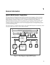
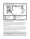
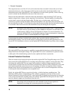

1 - General Information
12
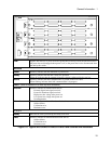
RS-232
PORT A
RS-232
PORT B
A
B
C
D
E
F
+ and - Power bus connectors
(- bus bar is connected to chassis ground)
Calibration status LEDs
Configuration switches
Transfer Calibration switch
Digital I/O connectors
LAN connection
G
H
J
K
RS-232 connectors (ports A and B)
AC line connection (a universal AC input for line
voltages from 87 Vac to 250 Vac, 50/60 Hz.)
Auxiliary output connection
Calibration port
Figure 1-3. Agilent E4370A/E4374A MCCD Rear Panel Connections
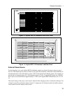
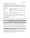
Agilent E4371A Powerbus Load
For the discharging cycle, an Agilent E4371A Powerbus Load is required to dissipate excess power from
discharging cells. The load operates in constant voltage mode only and sequentially switches internal
resistors on and off to regulate the voltage on the power bus around a midpoint of 26.75 volts. The
number of load units required depends on the number of Agilent MCCD mainframes in your system.
Each Agilent E4371A Powerbus Load is capable of the full power from two 256-channel Agilent
E4370A MCCD mainframes.
The Agilent E4371A Powerbus Load has a + and a − power bus connector on its rear panel. There is also
a ground connection. To meet safety requirements, connect the ground terminal of the Agilent Powerbus
load to the ground terminal of the external dc source. The load receives its operating power from the
power bus. If the dc voltage on the power bus drops below 23.8 volts, or if there is no power available on
the power bus, the load will not operate. Note that the load is not programmable. It is set at the factory
for the correct operating voltage and does not require calibration.
The On/Off switch on the load simply connects or disconnects the load from the power bus. Note that the
internal fans draw approximately 1.5 amperes of current from the power bus.
CAUTION: When discharging its maximum rated power, the Agilent E4371A Powerbus Load
becomes hot to the touch.
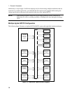
A
B C D E
G
F
H
K J