


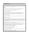
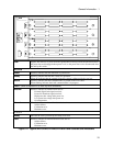
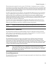
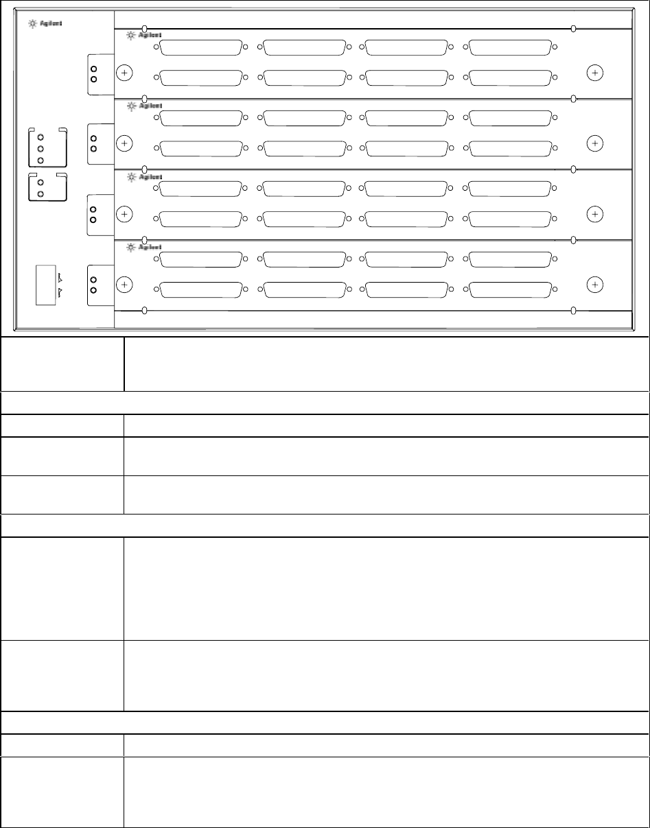
General Information - 1
11
1
Fault
Ready
SYSTEM
Power
Ready
Active
Internal
External
FAULT
Off
On
LINE
E4370A
MULTICELL CHARGER/DISCHARGER
2
Fault
Ready
3
Fault
Ready
4
Fault
Ready
1
2
3
4
5
6
7
8
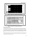
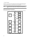
E4374A CHARGER/DISCHARGER
1
2
3
4
5
6
7
8
1
2
3
4
5
6
7
8
1
2
3
4
5
6
7
8
E4374A CHARGER/DISCHARGER
E4374A CHARGER/DISCHARGER
E4374A CHARGER/DISCHARGER
LINE
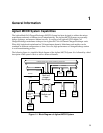
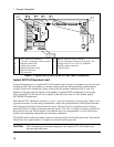
Applies and removes ac power from the Agilent MCCD. Relays inside the unit that connect
the power bus are disengaged when power is off, so the power bus is also disconnected from
the unit by this switch.
SYSTEM
Power
When lit, indicates that the mainframe is powered on.
Ready
When lit, indicates that the unit is ready for operation.
When off, indicates that the external power bus voltage is either too high or too low.
Active
When lit, indicates that data communication is present on the LAN cable.
When flashing, indicates that LAN communication is in progress.
FAULT (Refer to Appendix E to clear any fault conditions)
External
When lit, indicates an external fault such as:
External digital fault signal received,
Power fail shutdown signal received,
High power bus voltage after power on,
Low power bus voltage after power-on.
Overtemperature
Internal
When lit, indicates an internal hardware fault such as:
Selftest failure,
Calibration error,
Hardware error.
1, 2, 3, 4
Ready
Indicates the card is powered up and ready to be used
Fault
When lit, indicates an internal hardware fault such as:
Selftest failure,
Calibration error,
Hardware error.
Figure 1-2. Agilent E4370A/E4374A MCCD Front Panel Controls and Indicators