


3 - Configuration
42
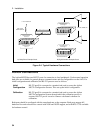
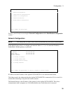
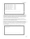
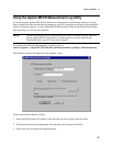
To continue configuring the Digital I/O, press 3. The pin numbers of the Digital I/O connector appear on
the screen. Refer to Figure 2-2 for the physical locations of the pins. Note that the two pins on each end
of the connector are the Common connection for any pins that are configured as grounded outputs.
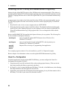
To configure a pin, select a pin number and press Enter. The following choices appear on the screen for
each pin that you select. Selections made in this screen will be shown in the previous screen.
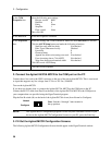
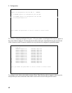
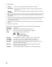
Digital I/O Configuration
Digital I/O Configuration over the LAN is ENABLED
1) To ENABLE Digital I/O Configuration over the LAN
2) To DISABLE Digital I/O Configuration over the LAN
3) To configure Digital I/O
Type a number and press Enter or ctrl-G to return to initial screen
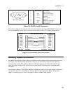
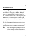
Digital I/O Configuration
Pin, Function
0 General Purpose I/O, Grounded, High True
1 General Purpose I/O, Grounded, High True
2 General Purpose I/O, Grounded, High True
3 General Purpose I/O, Grounded, High True
4 General Purpose I/O, Grounded, High True
5 General Purpose I/O, Grounded, High True
6 General Purpose I/O, Grounded, High True
7 General Purpose I/O, Grounded, High True
8 General Purpose I/O, Grounded, High True
9 General Purpose I/O, Grounded, High True
10 General Purpose I/O, Grounded, High True
11 General Purpose I/O, Grounded, High True
12 General Purpose I/O, Grounded, High True
13 General Purpose I/O, Grounded, High True
14 General Purpose I/O, Grounded, High True
15 General Purpose I/O, Grounded, High True
Type a pin number and press Enter or ctrl-G to return to initial screen