


General Information - 1
21
scanner, loading and unloading a test fixture, and manually starting the cell forming process. Chapters 5
and 6 describe all of the function calls that are available to implement a cell forming process.
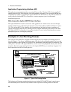
♦ The control PC sends a signal via the LAN to the digital I/O to turn on the Ready light on the test
fixture. This tells the operator that the system is ready for another tray of cells. The control PC also
begins polling for serial data on the RS-232 buffer of the Agilent MCCD.
♦ The operator scans the bar code on the tray of cells sitting on the conveyor belt. The operator then
loads the tray into the test fixture and closes the fixture.
♦ After detecting that data is available on the RS-232 buffer, the control PC reads the bar code data.
Based on the data, it downloads the correct forming sequence into the Agilent MCCD. It also
downloads setup information such as which channel outputs to enable, probe check settings, trigger
source, etc.
♦ The control PC then polls the digital I/O lines for the Start button.
♦ When the operator presses Start, the control PC detects it and polls the digital I/O lines to make sure
the fixture is closed. It sends a signal to turn off the Ready light and turn on the Test light, indicating
to the operator that the cell forming sequence has started.
♦ The control PC then sends a trigger to the Agilent MCCD to start the forming sequence. It also starts
polling the instrument status for the completion of the test sequence.
♦ The cell forming sequence runs. The test sequence automatically applies a stimulus to the cells,
monitors cell parameters to determine if a cell passes or fails, and stores the test results. During the
test sequence, the Agilent MCCD monitors the dedicated digital I/O lines that are connected to the
fire and smoke detectors. This allows rapid response in case of a problem.
♦ When the instrument status in the Agilent MCCD shows that the sequence is complete, the control
PC sends commands to the Agilent MCCD to measure the internal resistance of all cells and then
upload all measurement data.
♦ Finally, the control PC sends a signal to turn off the Test light and light the Ready light. The
operator knows that it is now safe to remove the tray from the fixture and start another batch.
Chapter 7 contains several programming examples written in C. The purpose of these examples is to
show you how to implement the various functions of the Agilent MCCD so that you can develop your
own application programs. Program #2 matches the example described here.