


Configuration - 3
43
All pins do not have to be configured in the same way. Some can be used as isolated outputs while others
are single-ended I/O. Functions can also be mixed, with some pins being general purpose Digital I/O
while others have a specific purpose. Chapter 2 under “Digital Connections” provides further information
about the purpose and application of the digital I/O signals. Any pin can be configured for selections 1
through 7. The common ground pin is the return for these selections.
Selections 10 and 11 are the power fail signals. One is the input, to signal that a power failure has
occurred; the other is the output, to indicate when the shutdown state has been saved. Pin 13 is a special
purpose signal discussed under cfSetDigitalConfig in chapter 5.
Selections 8, 9, 12, and 14 are the isolated output selections, which require a dedicated pair. Dedicated
pairs are located on adjacent pins (0-1, 2-3, 4-5, etc.), up to a maximum of eight pairs. For example to use
the pair pin 0-1 as an isolated output, configure pin 0 to be the isolated output and do not configure pin 1.
Pin 1 is the minus connector of the output. Writing to or reading pin 1 has no effect. Isolated outputs
cannot be used as inputs.
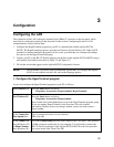
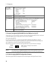
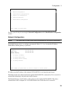
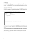
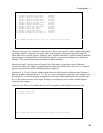
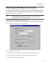
After you press Enter, select whether the pin will be configured as either High True or Low True.
Pin 0 Digital I/O Configuration
1) Change to External Fault Input Grounded
2) Change to External Fault Output Grounded
3) Change to External Interlock Grounded
4) Change to General Purpose I/O Grounded
5) Change to General Purpose Input Grounded
6) Change to General Purpose Output Grounded
7) Change to External Trigger Grounded
8) Change to External Fault Output Isolated
9) Change to General Purpose Output Isolated
10) Change to Power Fail Input Grounded
11) Change to Power Fail Output Grounded
12) Change to Power Fail Output Isolated
13) Change to Output and not Fault In Grounded
14) Change to Output and not Fault In Isolated
Type a number and press Enter or ctrl-G to return to initial screen
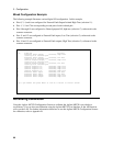
Pin 0 Digital I/O Configuration
1) Change to High True
2) Change to Low true
Type a number and press Enter or ctrl-G to return to initial screen