


2 - Installation
30
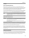
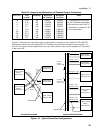
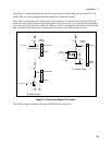
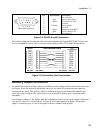
The star configuration on the left is designed so that each section of the power bus carries no more
current than the rating of the equipment that it is connected to. This configuration lets you use longer
lead lengths because the voltage drop in each lead is directly related to the amount of current flowing in
the lead. However, this configuration requires you to run separate leads from each Agilent MCCD
mainframe to the load as well as the power supply, thus increasing the total amount of wiring required.
The bus bar configuration on the right is designed to minimize the amount of wiring between the
equipment. However this requires larger diameter wires or bus bars. This is because the leads from the
power supplies as well as the leads to the load are required to carry the full charging and discharging
current for two Agilent E4370A MCCD mainframes. Larger currents result in larger voltage drops in the
wiring, which may prove unacceptable with long lead lengths.
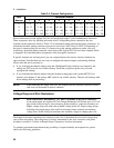
Charging Mode Guidelines:
Power bus wires must be capable of handing the full charging current requirements of all Agilent
E4370A MCCD units connected to the power bus. In the example that follows, the calculations are for
worst case current requirements. Calculate the input current requirement of one fully loaded Agilent
E4370A MCCD as follows:
1. Multiply the power used by one cell times the number of cells in the Agilent MCCD. Divide the
result by the efficiency of the unit to determine the total input power required for that mainframe.
The efficiency of the unit in charging mode is assumed to be 80%, which is a worst-case value as far
as calculating the total power required by the mainframe.
#_of_cells × power_per_cell
0.8
= Max_power_in
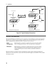
2. Divide the input power requirements of the Agilent MCCD by the minimum voltage required at the
input terminals of the Agilent MCCD. The result will be the maximum charging current required by
the Agilent MCCD. (Double this current if you are simultaneously charging two Agilent MCCD
mainframes as illustrated in Figure 2-1.)
Max_ power_in
Power_source_voltage
= Max_powerbus_current
3. Determine the voltage drop that the maximum current will produce in the power bus leads using the
resistance values in Table 2-6.
4. Add this voltage drop to the minimum voltage required at the input terminals of the Agilent MCCD
to determine the output voltage setting of the dc power supply.
5. The voltage at the input terminals of the Agilent MCCD during charging mode must be between 25.2
and 22.8 volts. If the sum of the voltage drops in both the + and − power bus leads causes the voltage
at the mainframe power terminals to drop below 22.8 volts, the Agilent E4370A MCCD will shut
down due to an undervoltage condition. Use a larger size wire to reduce the voltage drop.
Discharging Mode Guidelines:
Power bus wires must also capable of handing the full discharging current requirements of all Agilent
E4370A MCCD units connected to the power bus. In the example that follows, the calculations are also
for worst case current requirements. Calculate the output current of one fully loaded Agilent E4370A
MCCD as follows: