


Installation - 2
25
Location
Agilent E4370A MCCD Mainframe
The outline diagrams in Appendix C give the dimensions of your Agilent MCCD mainframe. The
mainframe may be installed free-standing, but must be located with sufficient space at the sides and back
of the unit for adequate air circulation. You can rack mount the mainframe in standard 600 mm (23.8 in.)
width system cabinets. This provides sufficient clearance for airflow. Support rails are also required
when rack mounting the mainframe. These are usually ordered along with the cabinet.
A fan cools the Agilent MCCD mainframe by drawing air in on the left side of the unit and discharging it
through the back and side. Minimum clearance is 9 cm (3.5 inches) along the sides. Minimum clearance
behind the mainframe is 23 cm (9 inches). Do not block the fan exhaust at the rear or the side.
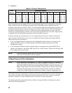
NOTE: To ensure proper cooling of the Agilent MCCD mainframe, there should be no open slots
in the front of the mainframe. If an Agilent E4374A Charger/Discharger Card is either
not installed or has been removed from a slot, a blank filler panel must be installed in the
opening. Refer to Table 2-2.
Agilent E4371A Powerbus Load
CAUTION: To ensure adequate airflow to cool the Agilent Powerbus Load requires you to leave 0.6
meters (2 feet) of open space in front of the load and directly behind the load. If you are
rack-mounting the load, leave the rack door off.
When discharging its maximum rated power, the Agilent E4371A Powerbus Load
becomes hot to the touch.
The outline diagrams in Appendix C give the dimensions of your Agilent Powerbus Load. The unit may
be installed free-standing, but must be located with sufficient space at the front and back of the unit for
adequate air circulation. Fans cool the unit by drawing air in on front and discharging it through the back.
Maximum airflow is 10 cubic meters per minute (350 cubic feet per minute).
You can rack mount the Agilent E4371A Powerbus Load in standard 600 mm (23.8 in.) width system
cabinets, provided that you remove the rear door. This provides sufficient clearance for airflow. Rack
mount kits are described in Table 2-2. Support rails are required when rack mounting the unit. To meet
safety requirements, connect the ground terminal of the Agilent Powerbus load to the ground terminal of
the external dc source.
Channel Connections
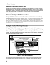
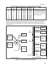
Each Agilent E4370A MCCD mainframe can control up to 256 individual charge/discharge cells when
four Agilent E4374A Charger/Discharger cards are installed. Each Agilent E4374A Charger/Discharger
contains 64 channels. Note that in the programming sections of this manual, channels are also referred to
as outputs. When fully loaded, the 256 charge/discharge channels are configured as follows: