


General Information - 1
19
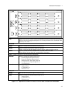
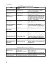
External Digital I/O Protection Functions
The Digital I/O subsystem on the Agilent MCCD can be configured to provide protection capabilities.
These digital I/O signals operate independently, so that if there is a problem with the computer or the
LAN connection the protection functions of the Agilent MCCD are not compromised. As explained in
chapter 2, the 16 digital I/O signals can be individually configured to provide one of the following
protection functions:
External Fault Input
This function can be used to stop the cell forming sequence if an external
fault condition sets the input true.
External Fault
Output
This function can be used to signal external circuitry or another Agilent
MCCD that either an external fault condition or an internal fault condition
has occurred.
External Interlock
This function can be used to stop the cell forming sequence for reasons
other than an external fault condition.
External Trigger
This function can be used to start a cell forming sequence.
In addition to protection capabilities, the digital I/O can also be used as general purpose I/O. When
configured as a general purpose I/O, the input or output signals on the digital connector are directly
controlled with API programming commands over the LAN.
If AC Power Fails
Should the ac line fail, the CPU in the Agilent MCCD will shut down. Any charging and discharging
activity will stop, and the current sequence, test data, and programmed settings will be lost.
Note: A 600 VA uninterruptible power supply (UPS) can be used to provide ac power to the
Agilent E4370A MCCD mainframe to prevent any data loss during a power failure.
When power fails, the power bus is also disconnected from the Agilent MCCD because of the bias
powered relays inside the Agilent MCCD. Thus, should a power failure occur which causes the Agilent
MCCD to lose ac power, in order to provide for safety, these internal relays would be disengaged and any
further charging or discharging would stop, even if the power bus were still powered and active.
Also, should a power failure occur which does not effect the Agilent MCCD but which causes the power
bus to drop in voltage, this will be detected by the Agilent MCCD as a power bus undervoltage condition
and the relays will open, thus preventing any further charging or discharging of connected cells.
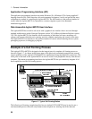
Remote Programming Interface
The remote programming interface to the Agilent MCCD is through a LAN-based TCP/IP
communication protocol. The connection to the LAN is through a standard 8-pin 10Base-T connector on
the rear panel, which must first be configured according to the directions in chapter 3. The LAN
communication protocol is implemented in two ways: