


1 - General Information
18
The comparison test to see if the ∆V, ∆I, and ∆t values have been exceeded is done at the end of each
measurement interval, so the fastest rate at which records can be written into the data buffer is the
measurement rate of the Agilent MCCD. Any combination of events can be specified, so that a data log
record is written into the data buffer when any of the events occur.
Each record in the data buffer contains the following information: status (including CV/CC and step
number), elapsed time, voltage, current, amp-hours, and watt-hours. The total number of readings that
can be stored is given in the specification table. The data log is a circular queue, which lets you
continuously log data into the data buffer. When the data buffer is full, the oldest data in the buffer will
be overwritten by new data. To avoid data loss, the controller must read the data from the buffer before it
is overwritten. Data can be read out of the data buffer at any time during the test sequence.
NOTE: Information in the data buffer is lost when an ac power failure occurs. To prevent data
loss in the event of a power failure, use the cfShutdown function to save the data in non-
volatile memory. Refer to Power Fail Operation in chapter 5 for more information. To
allow the Agilent E4370A to ride through temporary ac power interruptions, connect the
mainframe to a 600 VA uninterruptible power supply (UPS).
A measurement log utility is included in the software that is provided with the Agilent E4373A
Documentation package. You can use this utility to read the data log and place the information in a file
on your PC. For information on how to use the Agilent MCCD Measurement Log Utility, refer to chapter
4.
Protection Features
The Agilent MCCD provides extensive capability to protect both the hardware and the individual cells
being formed from catastrophic damage. The Agilent MCCD can also communicate its protection status
to other parts of the manufacturing system for more sophisticated forms of protection.
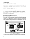
Internal Protection Functions
There are internal relays between the power bus and the Agilent E4374A Charge/Discharge cards. These
relays protect the Agilent MCCD from overvoltage and undervoltage conditions on the power bus. They
also protect the Agilent MCCD if an external fault condition is detected. Output regulators include
several features to protect the cell from failures in the hardware. Internal circuits connected in series with
each channel protect the system from reverse cell polarity, cell failure, and regulator failure. Internal
thermal sensors check for maximum heat rise to avoid failures due to excessive temperature excursions.
A fan keeps the internal temperature at an acceptable level.
Finally, the Agilent MCCD has an extra level of safety - a built-in hardware watchdog timer. The
hardware watchdog timer is independent of CPU, software, or firmware activities. If, due to some
internal firmware or software fault, the CPU in the Agilent MCCD should stop functioning for more than
a few seconds, the hardware watchdog timer will reset the Agilent MCCD to the power-on state. In this
state, the channels outputs are disconnected from the cells.
NOTE: Overvoltage and overcurrent tests can be included as part of a test sequence to
implement overvoltage and overcurrent protection (see chapter 5).