


2 - Installation
34
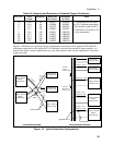
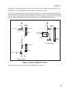
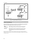
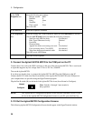
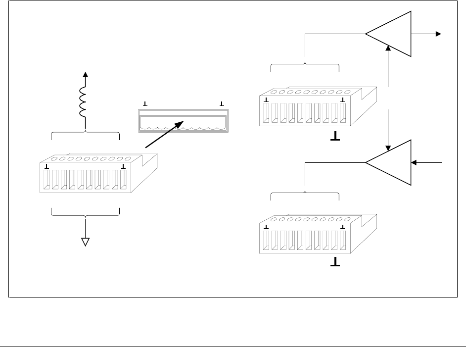
A) Relay Driver Example Circuit
. . . .
+ 16.5 V maximum
. . . .. . . .
connect to pins
2, 4, 6, 8
connect to pins
1, 3, 5, 7
Coil current
0.25A maximum
76543210
76543210
76543210
connect to pins
0 through 7
connect to pins
0 through 7
B) Digital Interface Example Circuit
TTL, AS, CMOS, HC
Connect common to
Connect common to
76543210
Figure 2-4. Typical Hardware Connections
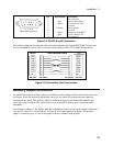
RS-232 Connections
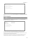
The Agilent MCCD has two RS-232 ports for connection to local peripherals. Under normal operation
both ports are available for general purpose communications and are configurable over the LAN. For
initial configuration and calibration, the RS-232 ports are used as follows:
Initial
Configuration
RS-232 port B is connected to a terminal and used to access the Agilent
MCCD Configuration Screens. This sets up the initial configuration.
Calibration
RS-232 port B is connected to a terminal and used to access the Agilent
MCCD Configuration Screens through which the calibration process is
executed. RS-232 port A is used to connect a dedicated voltmeter for
calibration.
Both ports should be configured with the same baud rate as the computer. Both ports support full
hardware flow and software flow control with XON and XOFF support, and with RTS / CTS available
for hardware control.