


Installation - 2
33
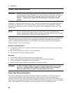
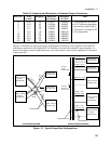
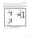
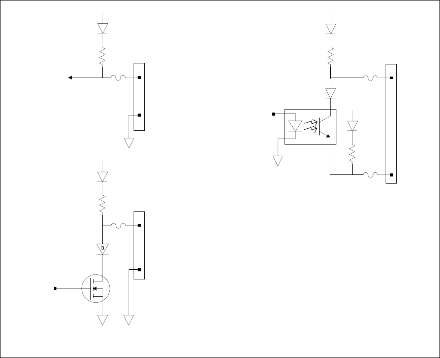
When used as a digital output (B) the external circuit connected to the output pin can also be TTL, AS,
CMOS, HC or a warning light, provided the light has an external bias supply.
When used as isolated pairs (C), each pin pair can be connected to external circuits with the following
restrictions: Only adjacent pairs can be used together. Only the even pin of each pair can be programmed
to set the logic level as low true or high true. When Low True is programmed, the output is true when the
pins are shorted. When High True is programmed, the output is true when the pins are open.
4.7K
+5V
Dig In signal
Odd or Even Pin
Dig Out signal
4.7K
+5V
Dig Out signal
Isolated
A. Digital Input
4.7K
+5V
B. Digital Output
4.7K
+5V
C. Isolated Output
DIG I/O
Connector
Odd or Even Pin
DIG I/O
Connector
Even Pin
Adjacent
Odd Pin
Common
Common
Figure 2-3. Equivalent Digital I/O Circuits
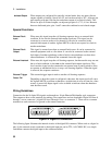
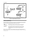
The following figure illustrates some typical DIO hardware connections.