


Installation - 2
35
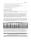
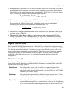
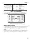
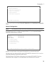
1 2 3 4 5
6 7 8 9
DB-9 male connector
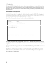
Pin
1
2
3
4
5
6
7
8
9
Input/Output
Input
Output
Common
Output
Input
Description
no connection
Receive Data (RxD)
Transmit Data (TxD)
not used
Signal ground
not used
Request to Send (RTS)
Clear to Send (CTS)
no connection
Figure 2-5. RS-232 A and B Connectors
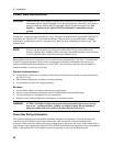
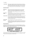
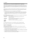
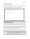
The following diagram describes the cable connections between the Agilent MCCD RS-232 ports and
any local peripherals such as a PC or barcode scanner. Refer to table 2-2 for cable kit information.
MCCD NULL-MODEM CABLE PC
DCD
RXD
TXD
DTR
GND
DSR
RTS
CTS
RI
1
2
3
4
5
6
7
8
9
1
2
3
4
5
6
7
8
9
DCD
RXD
TXD
DTR
GND
DSR
RTS
CTS
RI
DB9 MALE DB9 FEMALE DB9 FEMALE DB9 MALE
(or serial device)
Figure 2-6. Null-modem Cable Connections
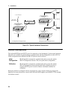
Auxiliary Output Connection
An undedicated isolated auxiliary output is provided to power various actuators and circuits local to the
test fixture. It can also be used as the pull-up source for any digital I/O connections that require an
external pull-up source. The auxiliary output is available through a 4-pin Phoenix/Weidmuller style
connector on the rear panel. The connector has screw terminals for making wire connections and is
detachable.
As explained in chapter 3, the Agilent MCCD Configuration Screens let you set this output to between 5
volts and 24 volts in 0.1-volt increments. 10 Watts of total output power is available. The auxiliary
output is isolated by up to 42 volts with respect to chassis common (earth ground).