TDS 620A, 640A & 644A User Manual
1Ć7
Setting Up for the Examples
All the examples use the same setup. Once you perform this setup, you do
not have to change the signal connections for any of the other examples.
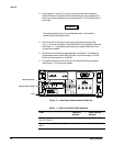
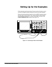
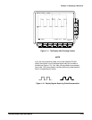
Remove all probes and signal inputs from the input BNC connectors along
the lower right of the front panel. Then, using one of the probes supplied
with the digitizing oscilloscope, connect from the CH 1 connector to the
PROBE COMPENSATION connectors (see Figure 1Ć3).
Figure 1Ć3:ăConnecting a Probe for the Examples


