Fast Fourier Transforms
TDS 620A, 640A & 644A User Manual
3Ć41
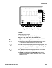
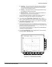
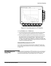
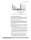
Figure 3Ć23:ăCursor Measurement of an FFT Waveform
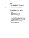
10. Press Function (main) ➞ Paired (side).
11. Use the technique just outlined to place the vertical bar of each paired
cursor to the points along the horizontal axis you are interested in.
12. Read the amplitude between the X of the two paired cursors from the
topĆmost D: readout. Read the amplitude of the short horizontal bar of
the selected (solid) cursor relative to either 1 V
RMS
(0 dB), ground
(0 volts), or zero phase level (0 degrees or 0 radians) from the @: readĆ
out. Read the frequency between the long horizontal bars of both paired
cursors from the bottom D: readout.
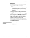
Automated Measurements of an FFT
You can also use automated measurements to measure FFT math waveĆ
forms. Use the same procedure as is found under Waveform Differentiation
on page 3Ć140.
There are several characteristics of FFTs that affect how they are displayed
and should be interpreted. Read the following topics to learn how to optiĆ
mize the oscilloscope setup for good display of your FFT waveforms.
Considerations for
Using FFTs


