


Appendix A: Specifications
TDS1000/2000-Series Digital Oscilloscope User Manual
165
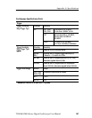
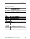
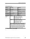
P2200 Probe Specifications
Electrical
characteristics
10X position 1X position
Bandwidth DC to 200 MHz DC to 6 MHz
Attenuation ratio 10:1 ± 2% 1:1 ± 2%
Compensation
Range
18 pf-35 pf Compensation is fixed; correct for
all oscilloscopes with 1 M Ω input
Input Resistance
10 M Ω ± 3% at DC 1MΩ ± 3% at DC
Input Capacitance 14.5 pf-17.5 pf 80 pf-110 pf
Rise time, typical <2.2ns < 50.0 ns
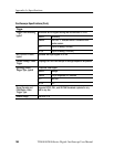
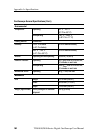
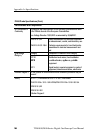
Maximum input
voltage
1
10X position 300 V
RMS
CAT I or 300 V DC C AT I
300 V
RMS
CAT II or 300 V DC C AT II
100 V
RMS
CAT III or 100 V DC CAT III
420 V peak, <50% DF, <1 s PW
670 V peak, <20% DF, <1 s PW
1X position 150 V
RMS
CAT I or 150 V DC C AT I
150 V
RMS
CAT II or 150 V DC C AT II
100 V
RMS
CAT III or 100 V DC CAT III
210 V peak, <50% DF, <1 s PW
330 V peak, <20% DF, <1 s PW
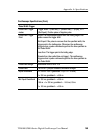
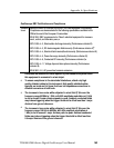
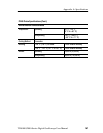
300 V
RMS
, Installation Category II; derate at 20 dB/decade above
900 kHz to 13 V peak AC at 3 MHz and above. For non -sinusoidal
waveforms, peak value must be less than 450 V. Excursion above 300
V should be less than 100 ms duration. RMS signal level including
any DC component removed through AC coupling must be limited to
300 V. If these values are exceeded, damage to the instrument may
result. Refer to the O vervoltage Category on the next page.
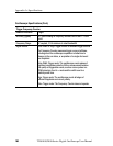
1
As defined in EN61010-1 on the next page.